Scratch UNF Pangaea Original Design / Scratch Built
Scratch - UNF Pangaea {Scratch}
Contributed by Les Bradshaw
| Manufacturer: | Scratch |
Brief:
Earth has recently developed Faster Than Light space travel. The United Nations Federation ship, the Pangaea was
built to bring United Nations delegates and ambassadors on an important diplomatic mission to meet with representatives
from the three main galactic empires.

This build is an attempt for the "Design This Spaceship" contest.
I've never tried to design a rocket from just a picture - especially when you don't have multiple photos that give you a 360 degree view. I've discovered that this is a very difficult process.
When I first considered participating, I looked over all the designs and tried to figure out which one provided maximum points. And then I procrastinated - so the final decision was based on the easiest.
I printed out the picture in two sizes. I started measuring and figured out the scale I wanted to use so I could select the parts. I figured the method to get the oval shape was to use multiple tubes in parallel.
Construction:
Parts you will need:
- BT-40 tube (Semroc)
- BTH-80 tube (Semroc)
- ST-9180 tube (Semroc)
- BT-5 tube (my parts pile - I think they came from Totally Tubular?)
- 3/16" x 6" balsa
- 3/32" x 3" balsa
- 3/32" x 4" basswood
- 1/16" x 3" basswood
- 1/8" dowel
- 1/4" dowel
- Kevlar® cord
- Elastic shock cord
- Parachute
- Launch Lug (I used 1/8" - I suggest changing to 3/16")
- bond paper
- Card Stock paper
- weights (I used BBs)
- BT5 to BT50 Centering ring (Semroc - 6 pack)(BT5 to BT 40 is really the correct size, but they were not available. I used the BT50 and cut/sanded down to size - you also need some of the BT50 size for the nose cone)
- CR-9115 Centering ring (Semroc)
- Michael's 40% or 50% (prefered)off coupon
- Estes Space Ship One Nosecone (use the coupon to get the kit cheap)
There is one main tube (Semroc size ST9 - close to a BT50) that runs the length of the rocket. The BT80H tube is used to create the oval body shape. Spacers and end caps are made from a mixture of 3/32" balsa and 3/16" balsa. The BT40 & BT5 are for the engines. Engine nacelles were made from the 1/16" basswood
The rocket has 2 main fins (3/32" basswood) with top and bottom "stabilizers" (3/32" balsa).
Why the mix between balsa and basswood - I started by using left over balsa that I had. When that ran out, I went to Michaels to get more, but their balsa stock was poor - but they had basswood so that's what I got.
An "exploded view of the rocket is shown below. Please note it is not to scale, or even proportion, but it will help give you an understanding of what pieces are what.

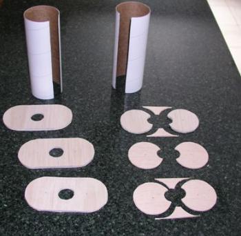 Start by using the attached template (template 1) to
cut some of the support pieces. There is a line to use as a sizing guide. It is 6" long, so when you print out the
template, adjust the size up/down until the line is 6". You need to cut the center circle first (save these pieces
for later) and then the other circles. For this step, you will use the inside of the tube circles. You will also want
to cut out and save the "triangles" between the two outer tubes. I started making these pieces from the
3/16" balsa. After the first one, I felt it was too difficult so I made 2 more from the 3/32" balsa. Please
look at the following picture to see what I mean by the triangle pieces - not shown are the center circle pieces.
Start by using the attached template (template 1) to
cut some of the support pieces. There is a line to use as a sizing guide. It is 6" long, so when you print out the
template, adjust the size up/down until the line is 6". You need to cut the center circle first (save these pieces
for later) and then the other circles. For this step, you will use the inside of the tube circles. You will also want
to cut out and save the "triangles" between the two outer tubes. I started making these pieces from the
3/16" balsa. After the first one, I felt it was too difficult so I made 2 more from the 3/32" balsa. Please
look at the following picture to see what I mean by the triangle pieces - not shown are the center circle pieces.
Using the same template as before, you need to cut 3 pieces from the 3/16" balsa using the outside dimension of the tube circle and only cutting half the circle. Connect the two circles so you end up an oval (see the picture above). Cut the center ST9 circle. These pieces are end caps for the BT80H/ST9 body.
Cut pieces from the BT80H tube, each 7" long.
Check that the "C" pieces fit inside the BT80 and on the ST9 tube. Use one of these C pieces to mark the BT80H tubes. Mark the tubes down their length and cut the tubes lengthwise. Check the fit of the BT80H, ST9, and C pieces together. Sand as necessary to fit.
Glue two of the C pieces into the BT80H flush with the ends of the tube. Glue the third C piece in the middle.
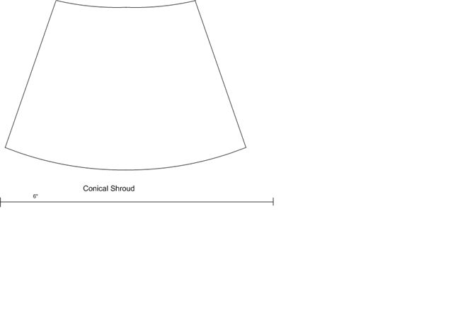
Next cut the smaller oval and the 2 circular rings from 3/32" balsa (Transitions Bulkhead Template). I beveled the edges of these to better align the edge with the shrouds.
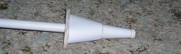
I had a little trouble with the shroud that went from round to "oval". I basically set up the balsa ends on the ST9 tube and wrapped paper and taped into place. I then marked and cut the paper to fit. I then used this as a guide to cut the real shroud out of card stock. I cut the card stock a little oversize. Cut a tab about 1/2" wide. Apply rubber cement to the tab and to the edges of the shroud. Wait for the glue to dry and then carefully apply the tab to one edge of the shroud (so half the tab is over-hanging). The cement is not forgiving, so you need to get it right the first try. Then curl the shroud and apply it to the other half of the tab. I then slid the shroud back onto the balsa ends and trimed to fit. Use the ST9 as a guide, glue the shroud to the balsa ring and oval piece. (templates Conical Shroud Template and Oval Shroud Template)
I also had to make a transition that was just round to round. While there are various programs you can get to do this, I again just used paper and tape, marked and cut to fit, and then cut the card stock to match. Again, use the tab and rubber cement to glue this transition together. Do NOT glue the transition to the balsa ring at this time.
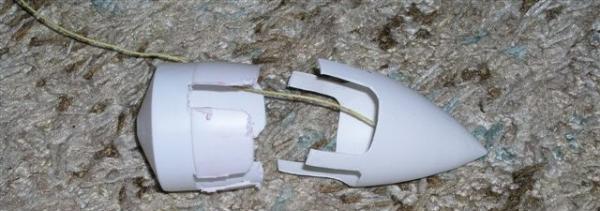
Open the Space Ship One and remove the nose cone. Mark the nose cone at four equidistant points around the shoulder. Centered from these points make marks that will be 1/4" wide. Measure up from the shoulder 7/8" and mark the cone. I used a Dremel cutoff wheel to cut along the marks. Try to round the inner corners.

Cut a length of BT5 tube about 3/4" long. Glue a BT5 to BT50 centering ring flush (or 1/16" in from the edge) and another 1/2" down from the first ring. Cut a piece of scrap ST9 about 1 1/2" long. Cut one of the CR-9115 rings to 3/8" long. Sand the pieces to have a smooth insertion for the BT5 to BT50 rings and the CR-9115 into and onto the ST9. Apply some epoxy to the edge of the BT5 tube (on the end away from the centering rings. Be careful not to get epoxy onto the ST9 or CR-9115 parts - these are only being used as guides. Slide the BT5, ST9, and CR-9115 into the nose cone as far as they will go. The ST9 and CR-9115 are to help center the BT5. Wait for the epoxy to dry, then remove the ST-9 and CR-9115 (save the CR-9115 for later). Cut a length of Kevlar® 8" long. Tie a loop into the end and some extra knots. Mix up a batch of epoxy. Slide the Kevlar® cord into the BT5 tube. Drizzle some epoxy down into the tube (be careful to not get any on the outside of the BT5 to BT50 centering rings. I started adding BBs and epoxy until the nose cone weighed 0.7 ounces. The epoxied BBs also help to retain the Kevlar® card.

On the 1/16" basswood, cut the nacelle pieces 3 3/8" long (Nacelle Template). You will need 4 pieces 1/4" wide, 4 pieces 15/16" wide, 2 pieces 1 7/8" wide, and 2 pieces 2 1/4" wide. Use the first template to line up the pieces and glue together. You will get a better joint if you bevel some of the edges. I applied a glue fillet to all the joints (inside and outside).
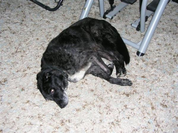
Next - disaster. Our old dog decided to "bless" my rocket with an ample amount of his "special water". Time to make some new shrouds and other pieces. Fortunately, the contest got extended.


For the engines, cut 2 pieces of BT40 2" long, 2 pieces of BT5 2 5/8" long, and 2 pieces of 1/8" dowel 3 1/8" long. As I indicated in the parts list, I actually had BT5 to BT50 centering rings. I had to cut down the rings to fit the BT40 tube. I used card stock to make centering rings to hold the 1/8" dowel into the BT5 tube (I glued 2 pieces of card stock together to make the "centering rings" stronger.) Using the centering rings, glue the dowel, rings, BT5, rings, BT40 together with the dowel, BT5, and BT40 centered lengthwise. After the glue is dry, paint the engine before assembling into the rocket.
Cut the wing fins (Wing Template) and stabilizers from the 3/32 basswood using the attached templates. ** NOTE ** After I built my rocket I realized the wings were heavy. I would recommend changing the wing to have a through the tube mount *** You will need 2 of each piece. Bevel the stabilizer edges that mate with the wing and glue the stabilizers to the wing. There is an angle guide for the stabilizers provided.
Cut 3 triangle pieces (Triangle and Bridge Template) from the 3/16" balsa. Glue the 3 pieces together. When dry, bevel and round the edges per the drawing.
Remember those circles originally cut out from the 3/16" balsa? Glue 5 together, slightly offsetting each one. When dry, sand the steps into smooth slope on the front, and sand to create a vertical back. Drill a hole through the unit from side to side. Glue in a 1 1/8" long piece of the 1/8" dowel through the hole. Cut a 1/8" long piece of the 1/4" dowel. Glue this to the top. Round the bottom to better fit the tube. This is the bridge section.
Cut the 2 detail pieces from 3/32" basswood.
Test fit the circular, conical transition section on the ST9 with its balsa ring. Slide it down the tube a bit. Slide the 3/8" long piece of CR-9115 from when the nose cone section was made over the end of the ST9. Place it flush with the tube end - do NOT glue at this time. Slide the nose cone onto the end of the ST9. It will push the CR-9115 down the tube slightly. Remove the nose cone and mark its position. Slide the transition forward until it touches the CR-9115 piece. Mark the position of the balsa ring. Remove the CR-9115 and the transition shroud. Using the balsa ring and CR-9115 positions, cut 2 pieces of 3/32" basswood to taper from the balsa ring to the body tube. These pieces will provide support for the "bridge" section.

Finally, cut 2 pieces of 3/32" basswood that are 1/4" x 1/4" and 2 pieces that are 1/4" x 3/8". These glue on top near the big triangle (see picture for approximate location)
Now to start putting it all together!
Using the marks from before, glue the transition balsa and the 2 support pieces to the ST9 about 1/4" apart. Mark where the support pieces are on the top edge of the ST9 for future reference. Apply a ring of glue around the ring and on the ST9 tube. Slide the shroud onto the ring and then finally glue the CR-9115 onto the ST9.
Glue the oval to circular transition onto the ST9 right behind the circular transition. Line the oval up with the support pieces (use the mark made before).
The next step you need to prepare for and should dry fit first. Slide 2 of the 3/16" endcaps onto the ST9. Slide the 2 BT80H sections onto the ST9. Rubber bands come in handy to hold these in place. Then slide the other endcap on the rear. Check the position of the BT80H tubes and the endcaps to make sure they all can be aligned. Once satisfied, apply glue to the rear of the oval transition, between the front 2 end cap pieces, the ends and C sections, and edges of the BT80H tubes, and then the rear end cap. Align all the endcaps and BT80H tubes together and with the oval transition. Use the rubber bands and tape to secure the BT80H tubes. Use tape to hold the end caps to the BT80H tubes. Once dry, sand (again I used a dremel tool) the front end-caps to get a rounded edge. Make sure to leave at least 1/8" of endcap flat on the BT80H tube side to glue the card stock to finish the body.

One new technique I used on this rocket was I covered the nacelles and fins with paper. I wanted to strengthen the parts, plus since I was running late I did not want to be tied up for multiple days sealing and sanding the balsa. I sprayed the pieces with 3M Super 77, applied the copy paper, and cut to fit. I then sealed the edges with CA.
Once the glue for the BT80H tubes and endcaps is dry, check the triangle pieces from the first cutting to fit. Glue these between the BT80H tubes. Glue one about 1" from the rear end cap to be a support for the glued up triangle piece.
Glue the wings onto the BT80H tubes. When dry, apply a fillet. Then cut some card stock to wrap around the BT80H/ST9 body (I applied this after the wings so I would have a wing to tube glue joint, and not a wing to card stock. If you change to through the tube you could apply the shroud first. I set up the card stock to wrap around the wing joint so the joint was on the bottom (a standard 8 1/2 x 11 sheet is not long enough). I applied a thin layer of wood glue on the BT80H and the end-caps and glued the card stock to the top. I used some tape to secure the card stock while the glue was drying. Once dry, I cut another piece of card stock to finish coving the bottom (again, applying glue to the BT80H and end-caps. Next, glue the engines to the BT80H so the center is in line with the and will be centered within the nacelles. Finally, glue the nacelles onto the BT80H. The corner should line up with the wing and the wing and nacelle will be touching.

Glue the rear triangle centered between the BT80H and even with the end.
To get the stepped look in the front, I glued a length of Kevlar® cord at the joint of the 2 transitions.

Glue the detail pieces on the top front. They should be resting on the supports under the shroud. Glue the bridge section in front of the detail pieces.
I finally cut the ST9 tube so only 1" extended beyond the rear end cap.
Use some of this extra ST9 to make an engine block. I cut two 1/4" wide sections. I slit one and slid it into the remaining spare section of ST9 tube (I did not want to risk the real tube at this point) to measure how much to cut off to fit inside the ST9. I slit the other and cut it down to size to fit inside the first slit piece. I glued the two together with the slits on opposite sides. Once dry, I then glued the engine block into the rocket using the standard technique (use a scrap piece of balsa to apply glue a little over 2" down, use a spent casing marked 1/4" from the rear end, push the ring in with the spent casing until even with the mark and then quickly remove the casing).
I used a standard Estes style trifold with over 2' of 1/4" elastic glued into the front of the ST9 for a shock cord. This is then tied to the Kevlar® cord attached to the nose cone. This point is where you will attach the parachute. I have multiple "stock" chutes with snap swivels that I reuse from rocket to rocket.
Finally, I glued a 6" length of 1/8" launch lug on the bottom. ** NOTE *** - When I flew the rocket, I found it was a bit too heavy for a 1/8" rod - I would update to a 3/16" launch lug *** I lined it up with the bottom of the BT80H tube (I wanted the tube to provide support, not just the card stock). This does make the launch lug off-center from the engine. I cut a piece of 1/8" dowel the same length and glued it on the other side. The contest picture does not show the rear or bottom so I have no idea what it should look like, but the dowel balanced out the layout. Assume they are conduits for the operation of the ship :-).
Finishing:
Use wood filler to fill in the gaps around the rear triangle and the front detail pieces to the card stock.
With the paper covering and shrouds, there is not a lot of exposed balsa. What was visible I used Elmer's wood filler (thinned down). A light white primer and some flat white paint provided the base coat.
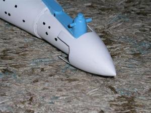
I flew the rocket with just this painting. After the flight (and repair - see below), I added the light blue and gray details shown in the picture. I used a Sharpie to make the port holes. I just use a pencil to draw in some of the other details. Below is a closeup of the nosecone and bridge area

 Flight:
I needed to go fly this bird to get things done for the Design This Spaceship contest. It was about 20 degrees out
with 10 ~ 15 mph winds, so the windchill factor was COLD. There was a dusting of snow on the ground. Not enough to
provide a soft landing, but enough to melt on your pants if you kneel the wrong way. Not the most ideal flying weather
(a bit windier than I prefer). I went to my local school yard and set up. Unfortunately, I discovered before I left my
daughter had borrowed my camera so I could not get any pictures at the launch site.
I built the rocket to use 24mm motors. There is no engine hook, so the motor has to be friction fit. I loaded the rocket with wadding (dog barf), and then the parachute. My first plan was to use an 18" chute but it was very stiff from the cold and I was concerned about it opening so I downsized to a 12". Wind gusts of over 20mph kept trying to blow my stuff away. I was thinking of waiting until later, but the weather forcast was for colder temperatures and winds in the 25 ~ 35 mph.
I used a D12-3 and used tape to secure the motor. I had problems with the tape due to the cold. I connected the leads to the igniter, but when I tried to move back the wire was stiff and pulled off the igniter. I pulled and straightened out the wires, reconnected to the igniter and waited for a lull in the wind. I pushed the button and nothing happened. I pressed again and held the button. I wind started to pick up so I decided to release the button to wait - just as it ignited. There was some rod whip - I should have used lugs for a 3/16" rod. It flew up nice and straight and ejection was after apogee. The chute opened but with the wind it was drifting away fast. I chased it as it was coming down. The descent rate was higher than I wanted. Oh, and did I mention it was bloddy cold out? No fluffy grass or soft, muddy dirt. No thick layer of snow. Nooo. The ground was rock hard! One stabilizer broke off and the wing was just barely hanging on. The other wing joint to the body tube was cracked. In some ways I was glad it broke - it gave me an excuse to come in from the cold!!!
I got home and I've repaired the rocket. I finished breaking the cracked joint and used epoxy to glue the wings back on. I made dams with tape and added epoxy fillets for the wing/tube joint. I re-primed and re-painted with flat white. I then added the marking/painting details. I used flat sky blue for the bridge and triangle and added a border on the nacelles and top stabilizers. I added a few of the grey rectangles on the nacelles and wings. Some of the other details I just drew in with pencil.
Now, can I fly again? Weather, overtime at work, “honey do” list with “its got to be done before the relatives get here.” The last Sunday before the contest ends – the weather is good and the wife went to the store. Can I sneak out? I start getting ready to leave when she returns. “Uhm – I have to go run an errand – be back soon” and I’m off to the school yard. Low winds, temperature in the mid-thirties – not too bad. I set up and launch.
Nice straight flight on a D12-3. Deployment about a second after apogee. I used an 18” chute this time. Descent was slower, but I still cracked one of the wing joints. It did not come off, but needs work before another flight. I put everything into the trunk of the car and return home and... BUSTED. The wife asks “How did the rocket fly?” Oh well – at least she didn’t yell at me – she understood that I had a deadline for finishing the rocket for a contest. I guess she knows me too well. (But I have been warned one way or another that certain things HAVE TO BE DONE by this Saturday.
Summary:
This was an interesting project involving many firsts for me. If I was to make another copy, I would make the main
wings a "through the tube" design. And make the launch lug for at least a 3/16" rod - there was too much
weight for a 1/8". Making the C shaped centering rings and slitting the body tube to create the oval shape does
give me some ideas for other designs. Developing the shrouds for the transitions involving a round to oval was also
interesting.
Sponsored Ads


 |
 |