| Construction Rating: | starstarstarstarstar_border |
| Flight Rating: | starstarstarstarstar_border |
| Overall Rating: | starstarstarstarstar_border |
| Diameter: | 0.74 inches |
| Length: | 5.50 inches |
| Manufacturer: | FlisKits  |
| Skill Level: | 2 |
| Style: | Multi-Stage, Saucer |

Brief:
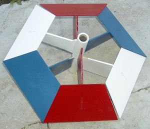
One of the few two-stage saucers on the market, Frick-n-Frack takes off like a fairly conventional 6-sided saucer. At
motor burnout of the first stage, the saucer separates into two sections, each with 3 drag-plate fins. The booster
section (Frick) tumbles gently to the ground while the sustainer section (Frack) continues to burn, often with a nice
spinning action.
Jim Flis showed the prototype for this at NARCON 2007 in February. Since I am a big fan of Art Applewhite's saucers, I immediately fell in love with Jim's Frick-n-Frack. Jim refused to sell me one in February, so I had to wait until the official release at the National Sport Launch in June. I ordered mine from JonRocket.com shortly after NSL and was pleased to receive production kit #84.
Construction:
Parts List:
- 2 2.75" BT-20 Body Tubes
- 3 Laser Cut Balsa Fin Sheets, 2 fins/sheet
- 3 Laser Cut Plate Sheets, 2 plates/sheet
- 1 Engine Block
- 2 1/8" Launch Lugs
- 1 Fin Alignment Template
- 1 Assembly Instructions

The laser cut balsa parts are very precise with very narrow cut lines. Like many Fliskits models, this one does not include any decals, leaving the decorative creativity to the builder.
Instructions are professionally printed on two sheets of 11" x 17" paper. Assembly instructions cover 20 steps, each of which includes a clear line drawing. Four additional drawings describe the flight preparation process and a full page drawing shows the unique two-stage flight profile.
The first step involves gluing a spent engine casing to the center of a full-page cardstock template. This template is used for all alignment steps. A body tube is placed over the spent engine casing so that the fins may be glued in place in later steps.
Step 2 suggests sealing the balsa since it will be much more difficult once assembly is complete. This is a good idea. I used a heavy coat of Kilz primer, which I later mostly sanded off. (Hint: The directions don't mention it, but the fin roots and locating tabs should be left bare to allow the glue to penetrate properly.)
Steps 3-7 cover gluing the sustainer fins to the body tube. A unique feature engineered into the kit is a stop tab on the fins. This tab allows accurate vertical placement of the fin. After the glue has dried, the stop tab is cut off flush with the end of the tube using a sharp knife.
 I had mixed feelings about the stop tabs. They are a great idea when building according to
the directions, and most builders should fine them quite useful. For builders like me who like to paint their parts
before gluing them together, the tabs made some of the dry-fitting steps more difficult.
I had mixed feelings about the stop tabs. They are a great idea when building according to
the directions, and most builders should fine them quite useful. For builders like me who like to paint their parts
before gluing them together, the tabs made some of the dry-fitting steps more difficult.
Step 8 repeats steps 3-7 for the booster section fins.
Steps 9-14 cover the attachment of the stabilizing plates to the tips of the sustainer fins. At each step, the plates are taped to the fin or to the template for proper alignment while the glue dries.
Steps 15-18 cover the attachment of the stabilizing plates to the booster fins. The booster plates must fit precisely between the sustainer plates so adjacent plates are taped together while the glue is drying.
After all the plates and fins are glued, a total of 24 fillets are applied while the parts are still taped together.
For the last two steps, launch lugs are attached to each stage and an engine block is installed in the upper body tube.
I am sure that the method described in the directions would have worked quite well and resulted in a very sturdy model. I wanted to do a three-color paint scheme that would have been a bit tricky after the parts were assembled, so I cheated a lot on the directions. I tacked each of the stabilizing plates to their respective fins using medium CA and a square to ensure that they were perpendicular. I then filleted each fin to its plate. After the fillets were dry, I painted all the fin assemblies.
I also primed the body tube before gluing the fins on. Normally when I do this, I use narrow masking tape to ensure that the fin contact area remains bare for good glue adhesion. I was on vacation when I built this kit so I did not have my usual assortment of tapes with me. I skipped the masking step, which later proved to be a mistake.
After all the paint had dried, I sanded each of the fin roots bare and tacked the fins to the tubes using medium CA.
Afterwards, I used Z-Poxy brand 5-minute epoxy to create fillets between the fins and tubes. This was the first time I have used Z-Poxy, and will probably be my last. Two days later, the epoxy was still sticky. In addition, the heat from the engine was enough to make the epoxy soft and flexible at the end of each flight.
Finishing:
I started by coating the raw balsa and cardboard with Kilz primer and sanding most of it off. I then painted each of
the fin/plate assemblies with Valspar enamel in three patriotic colors (Berry Red, Gloss White, and Pacific Blue).
Normally I would use Rustoleum paint and I would have repeated the primer/sanding steps until the grain was eliminated,
but I was on vacation and did not have all my usual finishing supplies with me.
No decals were provided, but the kit looks fine without them.
Construction Rating: 4 out of 5
Flight:
FlisKits recommends any combination of B6-0 and C6-0 motors for both the booster and the sustainer and suggests B6-0
under windy conditions to avoid weathercocking. The manufacturer does not recommend it, but any minimum-delay motor
(B6-2, B4-2, or C6-3) motor should work fine in the upper stage.
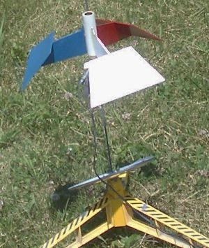
For my first flight, I used the recommended B6-0/B6-0 combination. Preparation consists of taping the two motors together using a single layer of clear tape then friction fitting each motor into its respective stage using masking tape. I found it somewhat tricky to get just the right fit in each tube, so that the stages would separate cleanly at first-stage burnout but each engine would remain firmly within its respective section. No wadding is required and no engine hook is provided.
Takeoff looked normal for a saucer of this size, going straight up to about 40 feet. When the upper motor lit, there was a loud pop. All the booster fins tore loose from the lower body tube and fluttered separately to the ground. Meanwhile, the upper stage continued up to about 100 feet with a slow spin. After burnout, the upper stage descended safely to the ground with a slow spin.
Post-flight examination showed that when the fins pulled loose from the lower body tube, they took the primer from the tube with them. Lesson learned: Always glue to raw material, not to a painted surface.
Flight #2 used just the upper stage with a B6-2 motor. This time it took off with a rapid spin and rose to about 50 feet.
After burnout, it arced over and tumbled for a while before settling into a gentle spin. The ejection charge fired about 15 feet from the ground. One fin broke loose on landing, again because the primer peeled off the tube. The loose fin was quickly repaired with a line of medium CA.
 Flight #3 flew with only the upper stage and used a C6-3. This time it spun quickly on the
way up to about 100 feet, arced over and spun on the way back down. The ejection charge fired at about 50 feet. The
landing was gentle with no additional damage. The heat from the motor did make the epoxy soft and flexible though.
Flight #3 flew with only the upper stage and used a C6-3. This time it spun quickly on the
way up to about 100 feet, arced over and spun on the way back down. The ejection charge fired at about 50 feet. The
landing was gentle with no additional damage. The heat from the motor did make the epoxy soft and flexible though.
Flight #4 again used a C6-3 in just the upper stage. The flight was a near-clone of flight #3, with apogee at 100 feet and ejection at about 75 feet on the way back down with similar spinning on the way up and down.
Recovery:
Even as a single-stage, Frack is a great flyer on a C6-3.
I have since repaired the booster, so I will be interested to see what a B6-0/C6-3 or C6-0/C6-3 combination looks like.
It might also be interesting to drag-race the upper and lower stages side by side. Not many rockets allow that as an option. (Note: Try this at your own risk. Stability of the lower stage by itself has not been tested.)
Flight Rating: 4 out of 5
Summary:
This is a very fun kit both to build and to fly. Getting all the parts aligned properly will require patience and
care, but the precision laser-cut parts and templates make it possible to do a very good job.
PROs: Unique 2-stage saucer design. Wild spinning flights. Low-altitude staging works well in small fields. Well-written directions and quality components.
CONS: Friction fitting the motors is a little finicky, and the staging is rather violent. A slightly larger body tube or a vent might tame it down.
Overall Rating: 4 out of 5
 |
 |
Flights
|
|
Sponsored Ads


|
|
W.T.M. (May 4, 2009)