Giant Leap Rocketry Avionics Bay (3.9-inch)
Giant Leap Rocketry - Avionics Bay (3.9-inch)
Contributed by Dick Stafford
| Manufacturer: | Giant Leap Rocketry  |
 Brief:
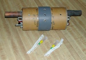
This avionics bay is made to be used with Giant Leap’s 4-inch flexible
phenolic tubing. It also fits in LOC’s 4” tubing, but you should
check the detailed dimensions on Giant Leap’s web site before planning to
use it with anyone else’s tubes. It features dual threaded rods and an
O-ring seal on one end. I added ejection cannons, electrical connectors, audio
plugs to break the ejection charge circuits, and a mounting board for my G-Wiz
altimeter.
Modifications:
Thee kit comes with two pages of illustrated instructions that show you how to
assemble the unit, mount your electronics, and use it in your rocket. The
intended use is to mount it between the drogue and main tubes in a
dual-deployment rocket. The electronics bay basically consists of a piece of
coupler tubing with two bulkheads that are clamped on either end by sections of
all-thread. There is an eyebolt on both ends for attachment of the recovery
system. All the required holes are pre-drilled.
One bulkhead sits on the outside of the coupler. The all thread is attached to this bulkhead using bolts and washers on both the inside and outside. Giant Leap recommends that these connections all be epoxied in place. On the opposite end, you epoxy the centering ring just inside the coupler. The O-ring sits against this ring and the second bulkhead, which fits inside the coupler, seats against the O-ring. Once clamped down, this provides a gas-tight seal. The all-thread fits through this second ring and wing nuts are used to hold it all together.
 The drawbacks I saw
were: 1) the tube is only positively sealed on one end (however, it appears to
me that the other end fits tight enough to be essentially gas-tight); 2) there
is no provision for routing wires through the bulkhead; and 3) there is no
place to mount/hold the ejection canisters.
The drawbacks I saw
were: 1) the tube is only positively sealed on one end (however, it appears to
me that the other end fits tight enough to be essentially gas-tight); 2) there
is no provision for routing wires through the bulkhead; and 3) there is no
place to mount/hold the ejection canisters.
Since I wanted some method of externally breaking the path to the igniters, I added a 2” piece of tubing at the center of the coupler. Mounting holes for the phono jacks were drilled in the coupler and outer tube. The latter was drilled to fit their mounting nuts (the jacks are flush with the outer tube). I drilled three holes, even though only two jacks are needed (to help with pressure equalization).
I bought this electronics bay to use in my Landshark, which is a 4” dual-deployment rocket that uses ‘zipperless’ separation. I needed to attach the bay to both the drogue and main tubes, and to make sure it stayed put. I first marked and drilled four holes on each end of the coupler. I then marked the basswood slats to match, inserted T-nuts, and epoxied them inside the coupler tube. The hex-head bolts were inserted to keep the slats aligned. I had to be very careful not to get epoxy on the T-nuts!
The ejection cannons consist of a copper cap, which is bolted to each bulkhead. Another hole was drilled on the side of the cap to accept the leads form an electric match. A small piece of copper tube is press-fit into the cap.


For external electric connections, I chose screw terminal banana jacks. In addition to the banana jack (which is unused), these offer a way to tightly clamp a wire that is inserted through a hole in the terminal. I drilled small holes in the bulkheads to accept the jack’s terminals, which extend below its body. The jack is secured to the bulkhead with provided nuts and washers, and the wiring is attached via ring lugs.
 For an electronics
mount, I just cut a piece of thin plywood to fit across the all-thread. Between
the all-thread, basswood strips, and wiring, the mounting plate is held in
place well (i.e. it doesn’t bounce around inside). The wiring for the
electric matches runs from the banana plug, through the phono jacks (one leg
only) and to the G-Wiz. Externally, the ejection charge is inserted into the
cannon with its leads running out the side, and is connected to the plugs.
For an electronics
mount, I just cut a piece of thin plywood to fit across the all-thread. Between
the all-thread, basswood strips, and wiring, the mounting plate is held in
place well (i.e. it doesn’t bounce around inside). The wiring for the
electric matches runs from the banana plug, through the phono jacks (one leg
only) and to the G-Wiz. Externally, the ejection charge is inserted into the
cannon with its leads running out the side, and is connected to the plugs.
Construction:
Components provided by Giant Leap:
- One 7” phenolic coupler
- One bulkhead that is the same diameter as the coupler
- One bulkhead that fits inside the coupler
- One centering ring that fits inside the coupler
- One O-ring (ring OD = coupler ID)
- Two ¾” eyebolts, with washers and nuts
- Two pieces of ¼” all-thread
- Two sets of nuts and washers for the all-thread (for one end)
- Two wing nuts and washers (for the other end)
Components I added:
- One 2” section of Giant Leap 4” tube
- Two ¾” copper caps
- Two ¾” copper tubes ~2 ½” long
- Two banana plug jacks with screw terminals
- Two ¼” phono jacks, with plugs
- Four 6.75” sections of 1” x ¼” basswood
- Eight T-nuts and eight hex-head bolts
- Plywood to mount the G-Wiz
- Misc. nuts and bolts
- Misc. wire
Flight:
I have flown this electronics bay twice, and it worked great both times. I used
the old-style ejection canisters from Pratt Hobbies. These consist of an
electric match embedded in a small plastic vial and fit perfectly into the
ejection cannons.
Summary:
This is a basic altimeter bay, which provides a gas-tight housing for your
electronics. It would be easy to build a similar bay from scratch, but this way
you get many of the piece parts in one kit. However, the user will have to make
some modifications to make it fully functional. Sure, the electric matches can
be routed through a small hole, the ejection charges could be taped to the
plate, and no one makes you break the leads to the charges, but most people
will want to do a bit more.
Wire routing is the main issue with my enhanced design. It takes some patience to get the mounting plate and wiring all nicely tucked into the bay. Other than that, it is easy to use and works well.


 |
 |