Scratch Clustered Booster Insanity Original Design / Scratch Built
Scratch - Clustered Booster Insanity {Scratch}
Contributed by Matthew Bond
| Manufacturer: | Scratch |
Brief:
Clustered Booster Insanity (CBI) was originally conceived as an entry for EMRR's "Elevate Eleven" contest,
which would also meet the criteria for challenge #6 in the 2009 EMRR Challenge. A two stage rocket which uses central
24mm motor mounts in the booster and sustainer, and 9 additional 13mm motor mounts on the booster. Both booster and
sustainer use streamer recovery. The package can be flown with 4, 7 or 10 motors in the booster and will achieve 1500
to 2500 feet altitude depending on motor selection.
Construction:
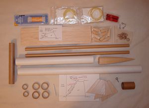
The CBI uses standard model rocket components which are readily available from multiple sources. Where appropriate, I
have called out the specific items used, but similar parts could be substituted easily. The following components were
used:
Sustainer:
- Main Body Tube BT-55--21"
- Nose Cone BNC-55ACP from Semroc
- Fins 1/8" Balsa
 Motor Mount Tube BT-50--2.75"
- 2 Centering Rings CR50/55--heavy paper type
- Thrust Ring CR20/50--heavy paper type
- Launch Lug--1/8" x 2.5"
- Kevlar® Shock Cord 150# - 36"
- Elastic Shock Cord--3/16" x 24"
- Mylar Streamer--4" x 56"
- Medium Sized Screw Eye
- Nose Weight--0.4oz of lead split shot (fishing weights)
Booster:
- Main Body Tube BT-55--3.25"
- Motor Mount Tube BT-50--2.75"
 2 Centering Rings CR50/55--heavy
paper type
2 Centering Rings CR50/55--heavy
paper type- Thrust Ring CR20/50--heavy paper type
- 9 Side Mounted Boosters BT-5--six 3" and three 5"
- 9 Thrust Ring CR10.5/13--heavy paper type
- 9 Nose Cones BC-512 from Semroc
- Fins 1/16" Balsa
- 3 Kevlar® Shock Cord 90# - 12"
- 3 Elastic Shock Cord--1/8" x 15"
- 3 Mylar Streamers--1" x 12"
- 3 Small Screw Eyes
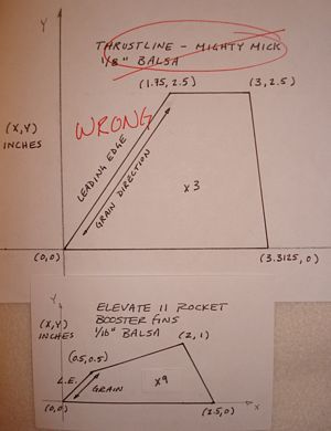
Before I describe construction of the CBI, a short discussion of the design effort is in order. As stated earlier, this rocket was originally intended as an entry in the EMRR Elevate Eleven contest. One of the earlier "suggestions" posted for that contest was to design a rocket with eleven stages (yeah right). It got me thinking though and I wondered if I could design a staged rocket that used 11 motors...or how about a booster with 10 motors lifting a sustainer with the 11th motor! I spent many hours playing around in RockSim and went through quite a few design iterations before arriving at the basic CBI concept. That concept went through several changes before I settled on the final design. One thing that drove the design that in hindsight seems kind of silly is that I had a set of fins that I wanted to use for the sustainer. These fins had been cut out for a clone that I was working on, and after I cut them out I realized that they were not the correct shape. They were too nice to just throw away, but I was getting annoyed looking at them and was determined to put them to use. To make a long story short, the design would have been better off with smaller fins on the sustainer and larger fins on the booster, but I had set that design point and did not allow myself to stray... Lesson learned.
Construction of the actual rocket was fairly straightforward. The sustainer is essentially a simple 3FNC and the booster, while offering some alignment challenges was not too difficult. All parts were joined with Titebond wood glue except where noted. Overall I would rate this somewhere just beyond a skill level 2 effort.
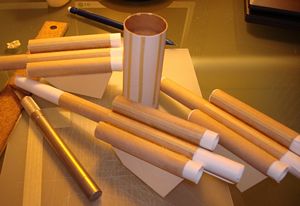
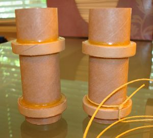 The main motor mounts were
constructed first and are identical except that the sustainer mount also serves as the anchor point for the Kevlar®
shock cord. In an effort to keep the weight down I did not install motor hooks in any of the mounts, although I did use
thrust rings. The centering rings are installed 3/4" from the aft end and 1/2" from the forward end of the
motor tubes. The thrust rings are installed flush with the forward end of the motor tube. The Kevlar®
shock cord is tied around the sustainer motor mount and threaded through a notch on the outside of the forward
centering ring. The motor mounts were installed flush with the aft ends of both body tubes, and all centering ring-body
tube joints were filleted.
The main motor mounts were
constructed first and are identical except that the sustainer mount also serves as the anchor point for the Kevlar®
shock cord. In an effort to keep the weight down I did not install motor hooks in any of the mounts, although I did use
thrust rings. The centering rings are installed 3/4" from the aft end and 1/2" from the forward end of the
motor tubes. The thrust rings are installed flush with the forward end of the motor tube. The Kevlar®
shock cord is tied around the sustainer motor mount and threaded through a notch on the outside of the forward
centering ring. The motor mounts were installed flush with the aft ends of both body tubes, and all centering ring-body
tube joints were filleted.
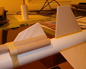
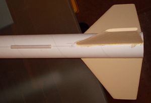 The sustainer was marked using a
standard wraparound template, and the fins were attached using a double glue joint. A second fillet of wood glue was
also added. The launch lug was attached on a line just next to one of the fins, 5" forward of the aft end of the
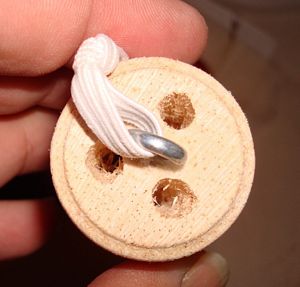
sustainer to allow for clearance of the booster section. The eyelet was attached to the nose cone by screwing it most
of the way in, removing it, adding a large drop of medium thickness CA and then screwing it all the way down. Final
assembly involved tying the elastic to the Kevlar®
and then to the nose cone.
The sustainer was marked using a
standard wraparound template, and the fins were attached using a double glue joint. A second fillet of wood glue was
also added. The launch lug was attached on a line just next to one of the fins, 5" forward of the aft end of the
sustainer to allow for clearance of the booster section. The eyelet was attached to the nose cone by screwing it most
of the way in, removing it, adding a large drop of medium thickness CA and then screwing it all the way down. Final
assembly involved tying the elastic to the Kevlar®
and then to the nose cone.
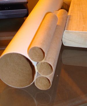
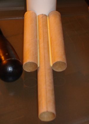
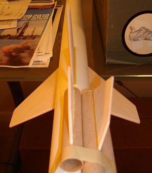
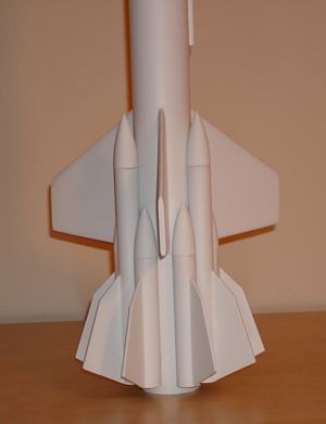
The booster section was constructed as four separate sub-assemblies to allow for easier finishing. The outside pod assemblies were each constructed with three clustered motor tubes. This arrangement allowed for the most clearance possible between the sustainer fins and the booster pods and also gave enough clearance for the launch rod. The three BT-5 body tube sections for each pod assembly were tacked together using a section of BT-55 as an alignment guide and then fillets were applied to reinforce the joints. After considering several ideas for attaching the fins to the pod assemblies, I used a scheme where the pod assembly was taped down to a section of BT-55 which was then slid into place behind the sustainer with a section of tube coupler. The whole assembly could then be rotated until each booster tube was inline with a fin on the sustainer, and the corresponding booster fin was then aligned via calibrated eyeball to the sustainer fin. All 9 booster fins were then given a second fillet of wood glue. A 13mm thrust ring was installed in each of the nine 13mm side pods. The 5" center section of each pod assembly would hold a small streamer to aid in recovery so the thrust ring for those tubes also had a length of Kevlar® string tied around it.
Finishing:
Finishing a rocket with any kind of tube fins or side pod assemblies is challenging. The best results are usually
achieved if the tube fins/pods are finished separately and then attached to the main body tube. I had purposely built
the CBI in this fashion, but I must admit that I put minimal effort into the final finish of this particular rocket.
Part of the reason was that I was trying to meet the deadline for the Elevate Eleven contest (although I didn't make
it), and part of the reason was that I was just about out of patience for this build and needed it to be over. This
rocket did not get any filleting work with the Elmer's Wood Filler (easy enough to justify on the basis of weight). All
the balsa parts got a single coat of thinned down wood filler to hide the worst of the grain. The booster body tube and
booster pods were all masked off prior to paint to allow for subsequent assembly. A single heavy coat of primer was
applied. At this point, with the Elevate Eleven contest deadline at hand, I tacked the CBI together and took pictures
for my entry. I then carefully pried everything apart and continued the finishing work. I made no attempt to apply an
exciting paint scheme, simply choosing primary colors that I happened to have on hand. Even with simple colors, 10 nose
cones, and 12 fins to mask proved to be time consuming, and the results (poor) speak to the fact that I was in a hurry
at this point. It was a little deflating to realize that even though the painting was completed, I wasn't done with
this thing yet!
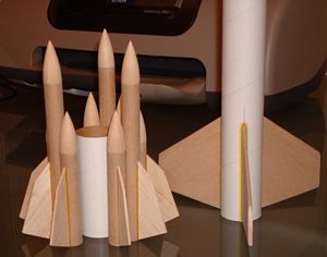
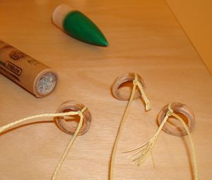
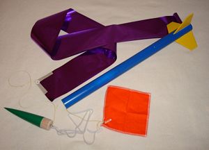
After all the paint was dry, I still had to assemble the booster. Before attaching the side pods, I punched a pressure relief hole in the top of the booster body tube and installed the tube coupler section. The tube coupler was test fit into the sustainer and sanded slightly to get a smooth fit. After some deliberation, I had decided that some type of standoff needed to be applied between the main booster body tube and the side pods. I had two main reasons for this. First I wanted to make sure I could get the motors into the small outside booster tubes, and second, I wanted to make sure there wasn't any interference between the booster and the sustainer. I cut strips from a section of BT-55 tube and glued them to the booster body tube where it had been masked off. Next the booster sections were glued in place. The nose cones for the shorter pod tubes were glued into place and this effectively limits motor choice for those tubes to the A10-PT, but I didn't figure I wanted to deal with 9 separate ejection charges anyhow. For the three longer pod tubes, a small screw eye was installed in each nose cone using CA glue, and then a length of elastic was tied to the screw eye and then to the Kevlar® thread anchored to the thrust ring. A small Mylar streamer was then attached to each recovery harness with a small swivel. The sustainer was also outfitted with a much larger Mylar streamer, which was protected by a Nomex® heat shield.
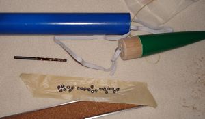 Finally I was nearing the end of
assembly and getting very excited about flying this bird! RockSim had indicated that some nose weight would probably be
required, especially to fly the full complement of 11 motors. With everything loaded up except the motors I weighed and
balanced the CBI and discovered that the RockSim prediction had been pretty close (RockSim said I would need 0.3oz of
nose weight and I ended up using 0.4oz). I used a drill bit turned by hand to bore holes in the nose cone and then
installed small lead fishing weights using wood glue.
Finally I was nearing the end of
assembly and getting very excited about flying this bird! RockSim had indicated that some nose weight would probably be
required, especially to fly the full complement of 11 motors. With everything loaded up except the motors I weighed and
balanced the CBI and discovered that the RockSim prediction had been pretty close (RockSim said I would need 0.3oz of
nose weight and I ended up using 0.4oz). I used a drill bit turned by hand to bore holes in the nose cone and then
installed small lead fishing weights using wood glue.
Flight and Recovery:
One of the biggest issues for me when I conceived this rocket was how to light a cluster of up to 10 black powder
motors. Up until now the largest cluster I had ever flown was 2. I started a thread on the subject on The Rocketry
Forum and was rewarded with a wealth of information. Everything from flash pans to flash paper was professed to be the
single most surefire way to reliably ignite large numbers of BP motors. About that time, Boris Katan also wrote a
detailed article in the May/June 2009 issue of Sport Rocketry magazine about igniting large clusters. Even
though Boris' system seemed to be overkill for my needs, his methods were instrumental in helping me come up with a
scheme. Eventually, the release of the new low current Q2G2 igniters from Quest offered up the best solution for me,
and the more I read about how well they were working for folks, the more comfortable I got. I procured a good supply
and did some testing with my trusty Estes launch controller. I had no trouble igniting 4, 7, or even 10 of the Q2G2
igniters, even with several of them wired in series. The only issue with using the Estes launch controller is that
there is no way to check continuity prior to launch. The controller actually passes too much current and will fire up
to 4 Q2G2s with just the safety key pressed down. In the field, I pressed the launch button down first and then pressed
the safety key to launch the rocket.
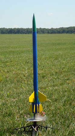
I snuck out at lunch one day to the local sod farm for the first (and last) flight of the CBI. Winds were light and fairly steady. I decided to go with one of the smallest motor combinations, a D12-0 and three A3-4Ts in the booster and a C11-7 in the sustainer. In order to minimize time at the field I had packed the streamers and loaded the motors the night before. As mentioned earlier, all motors were friction fit and small pieces of masking tape were used to achieve a tight fit on all motors. At the field, I installed the igniters and hooked up the whip clip. When the safety key was pressed all 4 motors lit instantly (the one launch photo I captured showed that two of the 13mm A10s ignited first) and the CBI jumped off the pad, arcing slightly into the wind. Staging was clean and the sustainer continued its arcing flight profile. I heard the ejection charges on the booster and caught a glimpse of the streamers as I was tracking the sustainer. Ejection occurred slightly after apogee as the rocket arced over, and the streamer deployed perfectly. I glanced at the booster and saw it hit the ground not far from the pad. The sustainer landed about 100 yards away, and it looked like a good flight! My elation was short lived, however, as I retrieved the sustainer and saw that one of the fins had popped off, most likely caused by the body tube buckling slightly, just above the engine mount on impact. The booster had fared much better. All three nose cones had deployed along with 2 of the 3 streamers, with one getting stuck in its body tube. All motors were retained and the booster suffered no damage at all.
In hindsight, I should have considered that fact that as I added weight to the nose of the sustainer, I was not only increasing the liftoff weight of the entire package, but also significantly increasing the recovery weight of the sustainer. Obviously a parachute would be more appropriate given the mass of the sustainer.
Summary:
I enjoyed the process of designing, building, and flying this rocket. It forced me to get out of my
"normal" zone and tackle some challenges I had never considered before. I am not satisfied that I have
learned enough from this project and will definitely be rebuilding the sustainer for future flights
PROs: A complex design that offers several challenges in terms of motor selection, launch, and recovery techniques. The symmetrical design of the booster allows for some flexibility in motor selection. Large clusters are impressive, even when the end result isn't perfect, and this one will be sure to impress once I work up to a full load in the booster.
CONs: A time consuming rocket to prep and fly. There are many potential "gotchas" that can spoil a flight if you aren't patient and methodical.
 |
 |
Flights
Sponsored Ads


|
|