Scratch Twice Removed From Yesterday Original Design / Scratch Built
Scratch - Twice Removed From Yesterday {Scratch}
Contributed by Dick Stafford
| Manufacturer: | Scratch |
Brief:
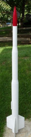
Twice Removed from Yesterday is a 4" diameter, 38mm rocket that
features two LOC plastic transitions. Although these transitions largely define
its external looks, the main thing that is different about its construction (at
least in my fleet) is the motor mount. The motor mount includes a LOC baffle
and a homemade retainer made from a PVC fitting.
Construction:
This rocket is largely a conglomeration of various LOC components from a
humongous ‘parts bonanza’ that I won in one of the r.m.r. Descons.
These LOC components used included:
- 1 54mm tube, 10" long
- 1 54mm-3" plastic transition
- 1 3" tube, 15" long
- 1 3"- 4" plastic transition
- 1 4" tube, 34" long, pre-slotted for 3 fins
- 1 38mm motor tube, 20 inches long
- 3 38mm-4" centering rings
- 1 54mm-4" ring
- 1 baffle kit for 38mm
As you can see, most of the rocket was free. I also borrowed the following from other existing rockets in my fleet: a 54mm cone, a ¾" tubular nylon shock cord, and my Rocketman R7 chute.
What I bought for the project is two eyebolts, a PVC fitting (male and female parts), a small piece of 38mm tubing for the future addition of an altimeter in the larger transition, and the wood for the fins (6 small sheets of 1/8" ply from Michael's).
I really wanted to try the baffle and the PVC fitting and somewhat threw the rocket together. I plan to return the nose cone to the original rocket and to reuse the smaller transition on another project. Thus, this rocket may only fly once in this configuration. I will most likely add a longer 3" tube and some sort of 3" nose cone. But I digress...
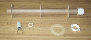 The components of the motor mount are laid out in the
accompanying photo. The smaller parts on the left comprise the LOC baffle. The
rings and body of the retainer are dry fit at this point. The 54mm ring will
reside on the end of the mount and will be epoxied to the main tube. The
retainer’s cap fits through the 54mm hole, but the tabs on the PVC body do
not. Thus, this will provide a little insurance in case JB Weld doesn't hold
well to the PVC.
The components of the motor mount are laid out in the
accompanying photo. The smaller parts on the left comprise the LOC baffle. The
rings and body of the retainer are dry fit at this point. The 54mm ring will
reside on the end of the mount and will be epoxied to the main tube. The
retainer’s cap fits through the 54mm hole, but the tabs on the PVC body do
not. Thus, this will provide a little insurance in case JB Weld doesn't hold
well to the PVC.
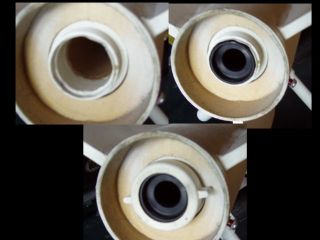 I used a Dremel to ream out the inside of the female portion of
the PVC fitting so it would fit over the 38mm tube and also trimmed the other
end to accommodate the rear closure of a Dr. Rocket case. This was not too
difficult, and to my surprise, I didn't ruin the thing. I made this so long ago
that I forgot the size of the fittings used, but this should be obvious if you
take a section of tubing with you to the hardware store.
I used a Dremel to ream out the inside of the female portion of
the PVC fitting so it would fit over the 38mm tube and also trimmed the other
end to accommodate the rear closure of a Dr. Rocket case. This was not too
difficult, and to my surprise, I didn't ruin the thing. I made this so long ago
that I forgot the size of the fittings used, but this should be obvious if you
take a section of tubing with you to the hardware store.
The LOC baffle consists of a piece of 29mm coupler tubing, a 3/8" retaining ring that fits in this coupler, a chunk of thick wire mesh, a 38mm OD centering ring, and a small piece of 38mm coupler tubing. You first epoxy the retaining ring into one end of the 29mm coupler. This ring keeps the wire mesh from blowing out the top of the baffle. The mesh is then folded tightly and inserted into the coupler tube. The 38mm ring is glued to the 29mm coupler and the 38mm coupler is then glued above that. Finally, the baffle assembly is epoxied in the motor tube. The baffle’s instructions say that it should be a minimum of 10 inches above the end of the longest motor. It so happens I had a 20" piece of motor tube, so that seemed like it should work fine.
The five components of the nose section are all held in by masking tape and friction. Even though the transitions have long shoulders, I was a little worried about it coming apart at ejection. So, I added some internal tethers to make sure the pieces stayed connected in the event they separated. As I said earlier, this rocket probably will be scavenged. If I were to keep this in my fleet, I would add some small screws to attach the components while keeping them removable. I also didn't trust the molded eyelet on the lower transition so I installed an eyebolt. To access the inside of the transition, I cut a small square from the its shoulder.
The fins are made from layered pieces of 3/32" ply. This is not the best method of fin construction, but I had much of the materials on hand. Even with thru-the-wall mounting, this material was way too flimsy, so I grabbed some more coupons and bought more 3/32" ply to add the outer sections. Once laminated together and well filleted, these seem OK. The results of this "experiment" will appear in the Flight section below.
The shock tether will connect to eyebolts on the top CR and the lower transition using quick links. The R7 will also be attached to the transition.
Finishing:
I couldn't decide on a scheme for this rocket so all it got was a lot of white
primer. This may be a good idea anyway, since I want to scavenge pieces for
another project. The cone was already bright red.
Flight:
I flew the TRFY on an I357T-10. The sim said the optimal delay was 9.65,
so the -10 is about right. Prep included attaching the shock tether and chute.
The PVC retainer made motor retention simple--a poor man’s
"Aeropack".
Recovery:
The flight was quick and deployment occurred just after apogee. Recovery was
perfect.
Summary:
The flight and the rocket were a success. I like to try out different things
and the baffle, homemade retainer, and "sandwich" fins all worked out
fine. I just may end up painting this rocket and buying an I600!
Sponsored Ads


 |
 |