Scratch Uranus Explorer 2 Original Design / Scratch Built
Scratch - Uranus Explorer 2 {Scratch}
Contributed by Tom Markel
| Construction Rating: | starstarstar_borderstar_borderstar_border |
| Flight Rating: | starstarstarstarstar_border |
| Overall Rating: | starstarstarstarstar_border |
| Published: | 2011-08-14 |
| Manufacturer: | Scratch |
| Style: | Ring/Tube/Cone Fin |
 Brief
Brief
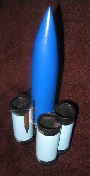
Personal Challenge: A working model built from and themed on Toilet Paper Rolls, Rear Ejection (of course!) and fly-able with C engines
Components
- 8 High-Quality Toilet Paper Roll Centers*
- BT 5
- BT 20
- Foam Board to make Adapter Rings
- Masking Tape (lots and lots of Masking Tape)
- Rubber Bands for Shock Cord
- Standard 12 inch parachute
(*Regarding "High Quality Toilet Paper Rolls," the cores from the industrial strength extra large rolls used in hospitals and office buildings by professional janitorial services are thicker, smoother, and tougher than the stuff you get at the grocery store. The spirals are however very deep.)
Construction
Challenge: Build a rocket based on theme of Uranus Explorer (but keep it PG rated)
At the same time I was building the rocket (actually the second rocket, the Uranus Explorer 1 was a dismal failure) I was making up a story that went along with the rocket. I think the best place to put that is up front in this review, so here it is.
INTERSPACE TELEX FROM SPACE COMMAND
URGENT: You have been ordered to take IMMEDIATE command of the Uranus Explorer II.
BACKGROUND: In the first half of the 21st century, concerns on Earth mounted regarding global warming. While there was a great uproar about changing human behavior to combat this menace, the problem solved itself in the second half of the century. While the well-meaning efforts of the "Greens," as they came to be called, may have had some impact, the finite supplies of fossil fuels expired by 2075. In addition, to fight the obesity epidemic, the fast food enterprises were vilified by the population. Ronald McDonald was hung in effigy in several countries. Since beef hamburgers were the main stock in trade for these restaurants, the demand for beef largely expired with the fast food franchises. The final major source of greenhouse gasses, the cattle farms, also went the way of the dinosaur. The global warming scare was over.
The loss of cheap fuel and fast foods led to a progressive sense of dissatisfaction among the people of Earth, who attempted to drown their sorrows in entertainment. VCRs and DVD players gave way to IPods, Androids, Playstations, Wiis, and other devices, all of which shared two features. First, they required electricity. Second, they were a mindless waste of time.
To replace the fossil fuels, the people of Earth maximized their use of renewable energy sources, including Wind, Geothermal, Hydroelectric, and Solar. The first three were largely limited by geography. Solar, however, was only limited by surface area. By the year 2125, solar "farms" had sprung up over much of the Earth’s surface, including Antarctica, and floating solar "mats" covered much of the oceans. Low Earth Orbit solar satellites created a virtual "traffic jam" in the skies, to the chagrin of terrestrial astronomers. Looking up at the sky at night, more stars "moved" than remained in once place.
The combination of the loss of greenhouse gas generators and the impact of solar collectors shading much of Earth’s surface as well as filling the skies had an effect that should have been anticipated--- the Earth's climate was heading for a second Ice Age. Temperatures plummeted.
Many different plans to restore the greenhouse gas "blanket" were attempted. A nationwide chili marathon was probably the most grandiose. It had little effect on the global atmosphere, but resulted in numerous hospitalizations throughout the state of Texas dues to the accumulation of noxious gases. In desperation, the people of Earth looked to the skies for help. The United States, once an importer of fossil fuels, now developed a plan to import greenhouse gases from space.
Of the four planetary gas giants, the highest concentrations of methane are found around Uranus, at roughly 2% of the atmosphere by volume. While further away than Saturn and Jupiter, manned expeditions to Uranus in 2186 found the planet had a rocky core with numerous central caverns. Concentrations of methane within the caverns approached 75%. Unlike Saturn and Jupiter, the caverns could be sealed, cleared of the methane, heated, and pressurized. In other words, there could be life inside Uranus.
Drilling operations began in 2192, and the planet was formally colonized under the leadership of Admiral Ezekiel Koli in 2199. The fecundity of E. Koli's descendents became legendary, and within 5 years the colonists had spread throughout the bowels of the planet. Methane gas generated within the rocky core was diverted to natural "vents" on the planet surface. This gas was collected in Surface Repositories (dubbed "SuPositories.") The SuPositories were then harvested by tanker ships and the gas was transported to Earth. The effort has been thus far successful. Earth's temperatures have stabilized and are gradually returning to 21st century levels. The only casualty was the state of Utah, which seceded from the Union when the restoration of "normal" temperatures forced them to abandon plans for year-round skiing.
During the drilling operations on Uranus, miners discovered rich deposits of Amodium. Existing in two chemical isomers, the "L" or levo form and the "D" or dextro form, Uranian Amodium was predominantly in the D isomer. Valued for its medical properties, Amodium-D is extremely useful in the treatment of dysentery. Earth's Amodium supplies were exhausted in the early 21st century in a vain attempt to stem the tide of large fecal outflows from Washington, D.C. Uranus produces 80% of the pharmaceutical grade Amodium-D in the solar system. The only other major supply of Amodium-D is in the asteroid belt. Tanker ships, notorious for poor hygiene, were plagued with dysentery and the production of Amodium around Uranus rivaled the methane mining operations in profitability.
The growing population inside Uranus yearned for the same amenities and distractions as their distant Earthly cousins. Entrepreneurs, ever anxious to make a credit, established venues on the Uranian satellites, including a Disney Theme Park, "Part of Your World," on the satellite Ariel, a Lane Bryant Woman's Clothing outlet store on the satellite Titania, and a romantic bed and breakfast getaway, "A Quiver of Love" on the satellite Cupid. By 2250, Uranian commerce had established a respectable amount of regularity.
Unfortunately, the hygienic habits of the Tanker ship crews did not improve. Due to failure in interspace decontamination procedures, one or more tankers have carried a type of "animal fungus" from the asteroids to the surface of Uranus. These vile creatures reproduce rapidly and are incredibly adherent to the rock and ice surface of the Uranian core. They are particularly attracted to the relative heat around the vents of Uranus. Dubbed, "Cling-Ons" by the colonists, the invaders have destroyed the SuPositories and have multiplied to the extent that they are now obstructing many of the methane outlets. The buildup of pressure behind the vents is reaching dangerous levels, producing dyspepsia, nausea, and vomiting among the population of the planet. Mining operations of Amodium-D have ground to a halt. Because there is no local supply, an outbreak of dysentery on the satellite Oberon has required importation of Amodium from the asteroid belt. This has put an incredible load on an already strained interplanetary supply system.
The situation is now CRITICAL.
We have deployed Remotely Operated Infrared Detectors (ROIDs) within all the major vents to monitor the situation. The ROIDs will detect focal temperature increases which herald obstruction. Additional SuPositories have been prepared to replace those destroyed by the Cling-Ons. The Jovian and Saturnine Fleets have been redirected to assist in the emergency.
The initial scout ship, the Uranus Explorer, was mothballed in 2195. It has been recommissioned for the rescue effort. The previous BVD-1 subspace engine has been upgraded to the BVD-2. The ship has also been augmented by 4 Procto and Gamble Sharmin "Ultra" outboard engines to give it interplanetary capability at 0.25 light speed.
Your mission is as follows:
- Rendezvous with the USS Colon Powell (commanded by Admiral Sigmoid Koli) and guide the Fleets in the evacuation of Uranus.
- Scour Uranus and wipe out the Cling-Ons.
- Monitor the ROIDs. At any hint of sensitivity, insert the replacement SuPositories to relieve the obstructed vents.
- Restore Amodium-D mining operations, to reduce the frequency and urgency of the runs between the asteroids and Uranus.
Addendum: On successful completion of this mission, you and your spouse are authorized a 30 day furlough at the "Quiver of Love" on Cupid. Remember, with 27 satellites, there is always a full moon around Uranus.
END TRANSMISSION
Back to the review. Goals of the rocket building were as follows:
- Had to look at least slightly cool
- Use Toilet Paper rolls for much or all of construction
- Rear End Ejection (naturally)
- Inexpensive project
- Standard (A, B, or C) Engine size (see #4)
- Write a background story.
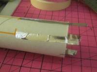
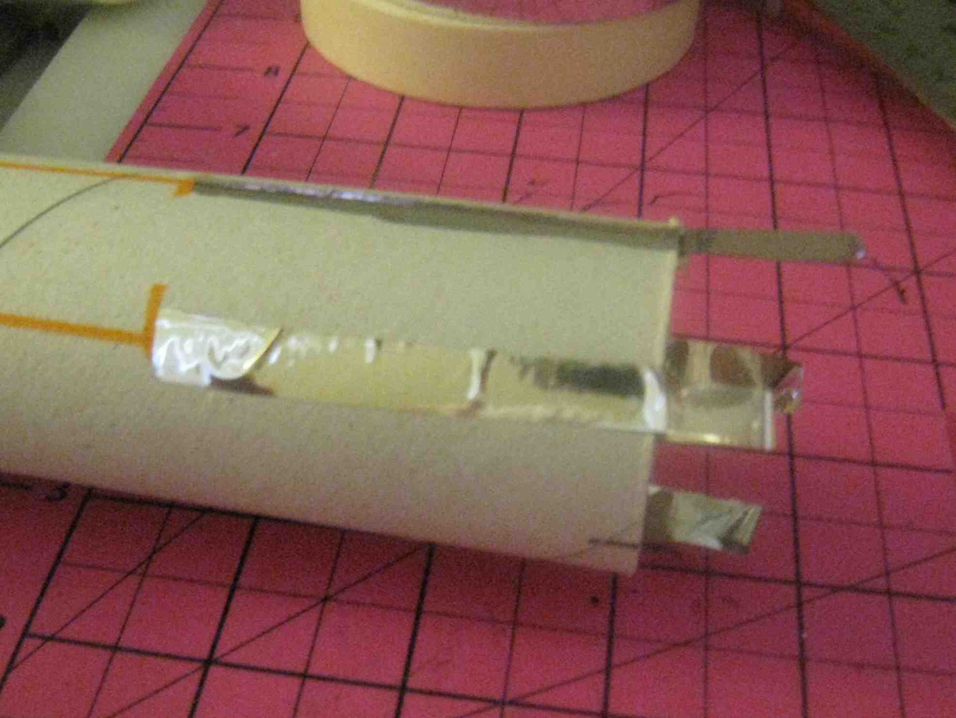
 After building the Estes Porta-Pot Shot, and reading notes from a reviewer who suggested a rear-ejection model, started to think of other designs sort of on the same theme. Original design became the Uranus Explorer 1 (UE1), (which will be fairly similar to the UE2, described here. I found that using only two rolls for the nose-cone fuselage combo resulted in a stubby rocket that I could not get stable (I know, I built it and tried. For some reason Tim Van Milligan doesn't have Toilet Paper tubes in the RockSim inventory. Go figure!) So to lengthen the fuselage, had to use two rolls connected (alternative would have been to use a single paper towel roll, but that would have violated the theme. Would have had to call it the Brawny or the Scrubber, or something else. But I digress...) You say, no problem, a coupler would work for this. Problem, since I pre-determined to use rear end ejection, I needed a pristine smooth inner contour, so a (standard) internal coupler wouldn't work. So I went with an external coupler. This of course was aerodynamically suboptimal, but since I wasn't planning to set an altitude or duration records, was acceptable. So I used an external coupler cut from another tube. I figured I would put the launch lug in the gap later (had I really thought it through, would have remember I could hide a launch lug in the tube fins.) This still left a small step-off or "transition" on the inside where the two tubes butted together. I ran masking tape from end to end along the inside so that there were no transitions to trap or catch the engine pod and recovery devices during rear ejection.
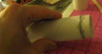
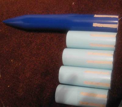
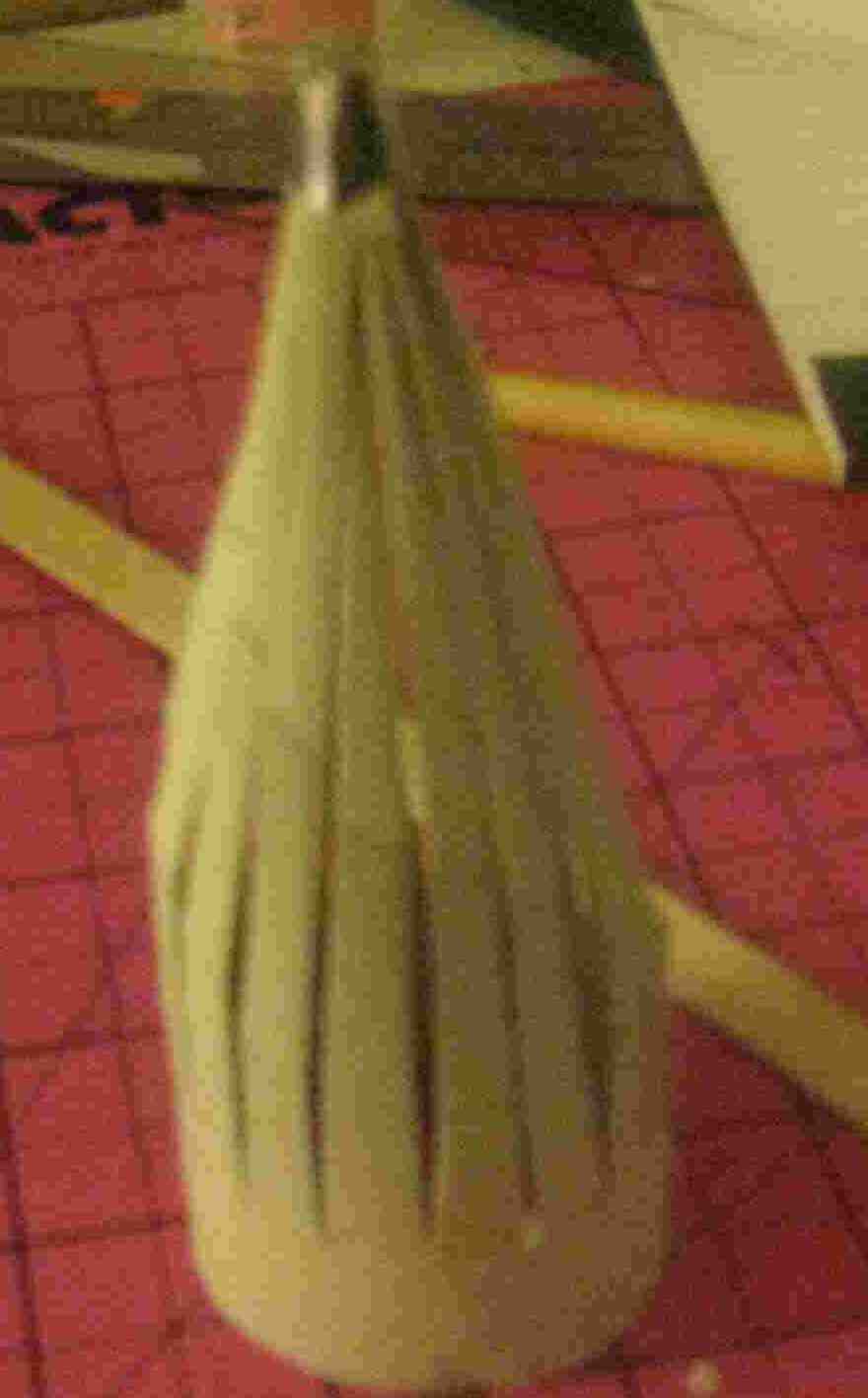
Next problem: the nose cone. First, not sure that toilet paper roll centers really come in a standard size for nose cones. Second, I'm cheap. Third, wanted to keep overall weight of the body of the rocket light (more on this later.) 4rth, wanted to use as many TP rolls as possible. Wondered---- how could I make a nose cone out of a toilet paper roll?
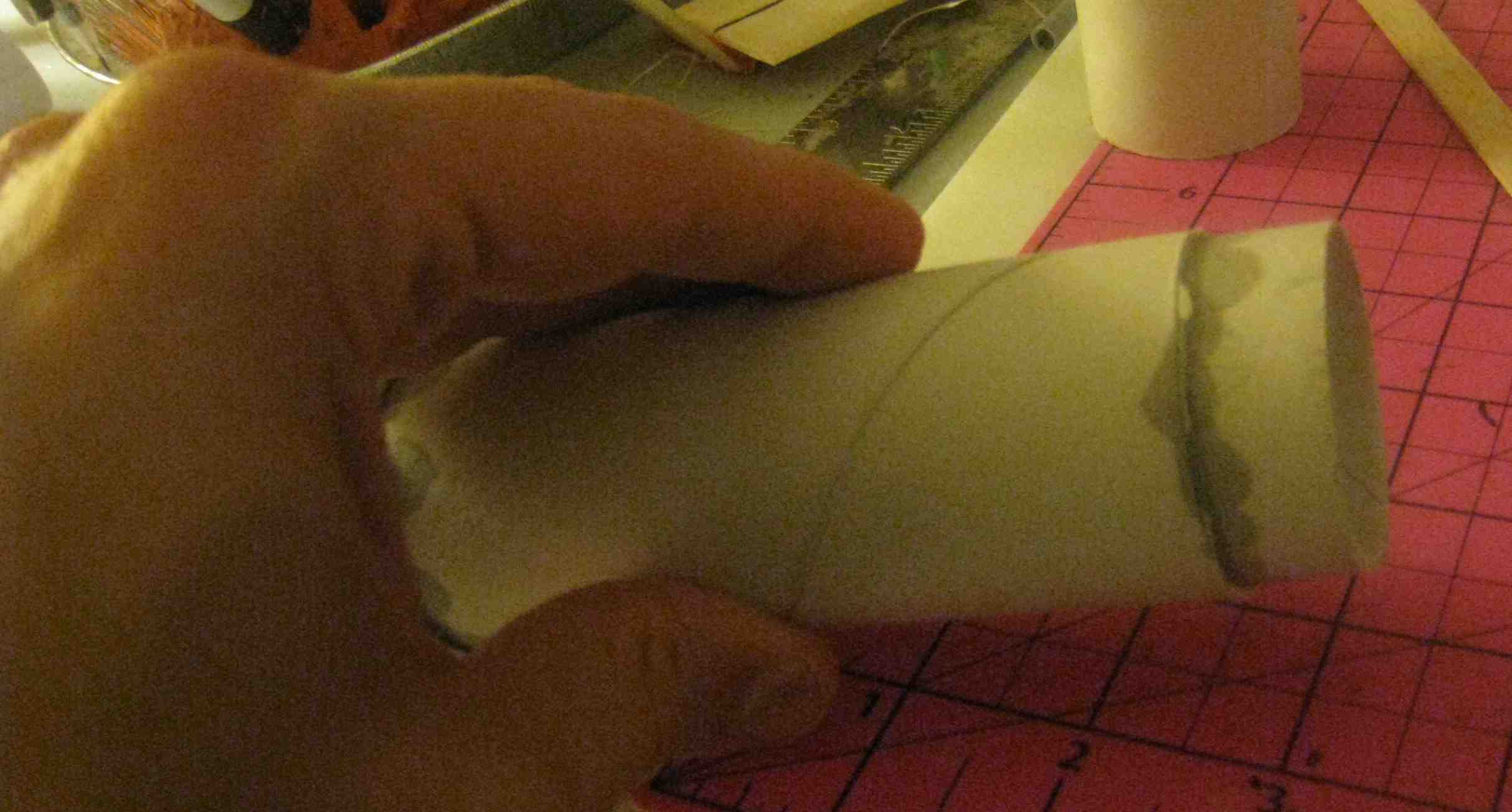
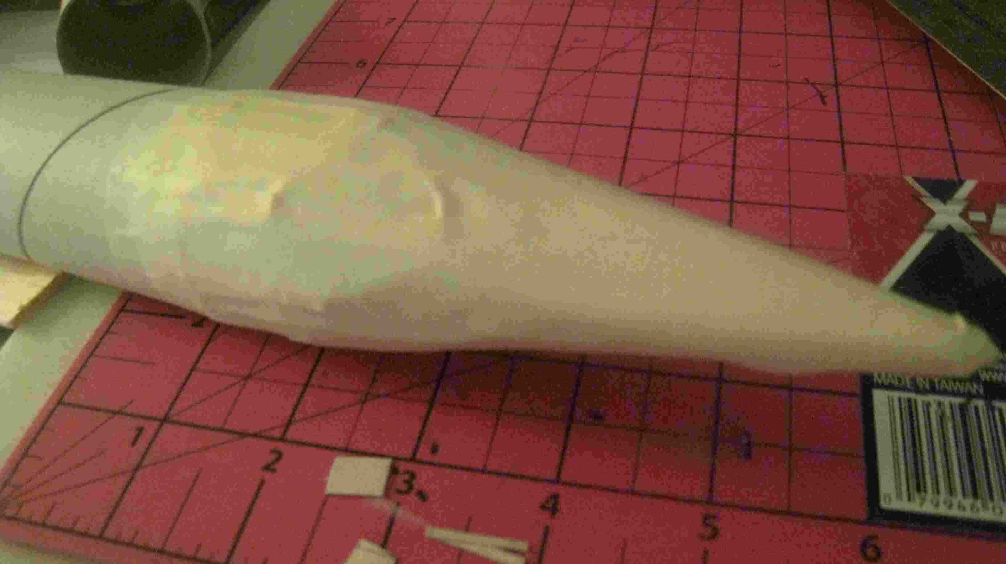
By cutting 16 length-wise cuts nearly to the end of the roll, then cutting a diagonal out of each section, I was able to create a roughly Ogive cone. Connected the tips with tape. Put a "shoulder" (again cut from another TP roll) on the anterior end of the body tube. Attached this with CA to the previous two tubes I now have a fuselage (one-piece with the nose cone) just under three TP rolls long I then ran strips of masking tape LENGTHWISE from just beyond the tip to just aft/tailward of the nose-cone/fuselage joint). At the tip, I cut the corners steeply and wrap around the nose cone. I had to run a few spiral wraps for support and to maintain shape.
 |
 |
|
Nose Cone
|
|
 Shoulder |
 Nose Cone/Fuselage |
Finishing
As mentioned, the building and painting run together as the painting was done before completely fitting together the parts.
Once I had the shape roughed out, it was time to fill. However, I wanted to have a clean paint job with different colors for the fuselage and the tube fins. I felt that masking would be tough. But if I painted them first, then I would be trying to glue together painted surfaces. That didn't sound like it would be to strong. On the other hand, I KNEW exactly where all the joints would be (I was using four tube fins, paired, on opposite sides of the fuselage. Since 6 tubes would fit perfectly, I just placed marks at 60 degrees, 120 degrees, 240 degrees, and 300 degrees on the fuselage. On the tube fins, two marks each, 60 degrees apart, would suffice. For increased stability, I let 1/2 of the tube fins lag behind the end of the fuselage (also thought would look cooler. Later during actual preparation of the rocket for launch I found it did make access to the engine mount awkward.) So marked on all the tubes where the joints should be. I also marked where I wanted to put the launch lug.
I wanted to "protect" the joint areas from the paint and sealer to set up a stronger joint. On the UE1 I had placed thin strips of masking tape over these areas. I discovered the masking tape broke down under the sanding process, so I tried Mylar tape strips, 1/4 inch wide. I placed a "tail" over the edge/lip of each tube, and then wrapped the very tip INSIDE the tube. Turned out the sanding still wore off most of the tails, but the tip piece wrapped inside was an adequate marker for removal of the tape later. Each strip was 1/2 the length of a single tube.
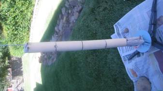
It took five coats/sandings of Elmer's filler to get a good smooth surface over the nose-cone masking tape. Therefore regarding "saving money" as a reason to make your own nose cone--Unless your time is worth less than 25 cents an hour, you’re better off buying it from Tim. But since this WAS a themed rocket, it seemed worth it. (Although my lovely wife wasn't happy about the pile of filler dust on the front porch!) I need three coats/sanding to fill the DEEP VALLEYS of the toilet paper roll spirals anyway, (another reason to use REAL body tubes.) I sealed the tube fins (outside only) the same way.
Note that since this is a rear-ejection model, it allowed me to cover the nose-cone/fuselage joint. While I was filling in the masking tape defects and the tube spirals, it turns out I had enough filler to cover the external coupler. In fact, by the time I was done the slight residual "bulge" was hardly notice-able. (Performance-minded rocketeers are probably shuddering at the added weight of the filler required to accomplish THAT.)

When I was finished, I had a very nice fuselage with a smooth surface from tip to tail, except for the "break" in the external coupler where I planned to put the launch lug. Again, had I been thinking, I would have filled this in too and put hidden the lug in the tube fin/fuselage joint. I believe the absence of a nose-cone/fuselage transition gives the rocket a retro Buck Rogers look. Of course, I also believe in the tooth fairy. Again, I digress......
I knew that trying to fill in the INSIDE spirals of the tube fins was going to be hopeless. I figured the insides of a spaceflight engine would probably look a little "charred", so I planned on painting the inside flat black and hoped that would hide the defects.
Okay, so painting now comes before actually completing construction. Before starting, I peeled back the edges of the Mylar at the distal edges of the tubes, to make sure I could find them after painting (painting the inside would obscure the "tails" I had wrapped on the inside of the tube.) The hard part was FINDING the edge. Many of the "tails" that I had thought would provide "handles" had been sanding off during finishing. But the tips that I had wrapped on the inside (unsealed) part of the tubes were still there. Using them as guides, I used an Exacto knife to peel back the edges of the Mylar tape on the OUTSIDE so I could find it after painting the inside. I wrapped newspaper around the OUTSIDE of the tube fins, taping it at the edges/lips. Then I used flat black paint to finish the INSIDE of the tubes. I actually tried rolled up sandpaper to reduce the "nap" inside the tube, but it didn't work very well. Primer would have helped, but I was having a struggle justifying trying to prime the INSIDE of the engines. Again, I figured I was going for style, not performance, so I gave up on that part. I sort of liked the internal "charred" look of the engines. As a prior Air Force guy, I noticed the nozzles of jet engines on the flight-line often had blackened look, so I felt I was okay with it for space engines.
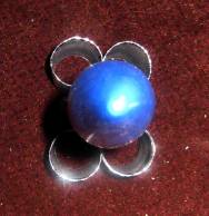
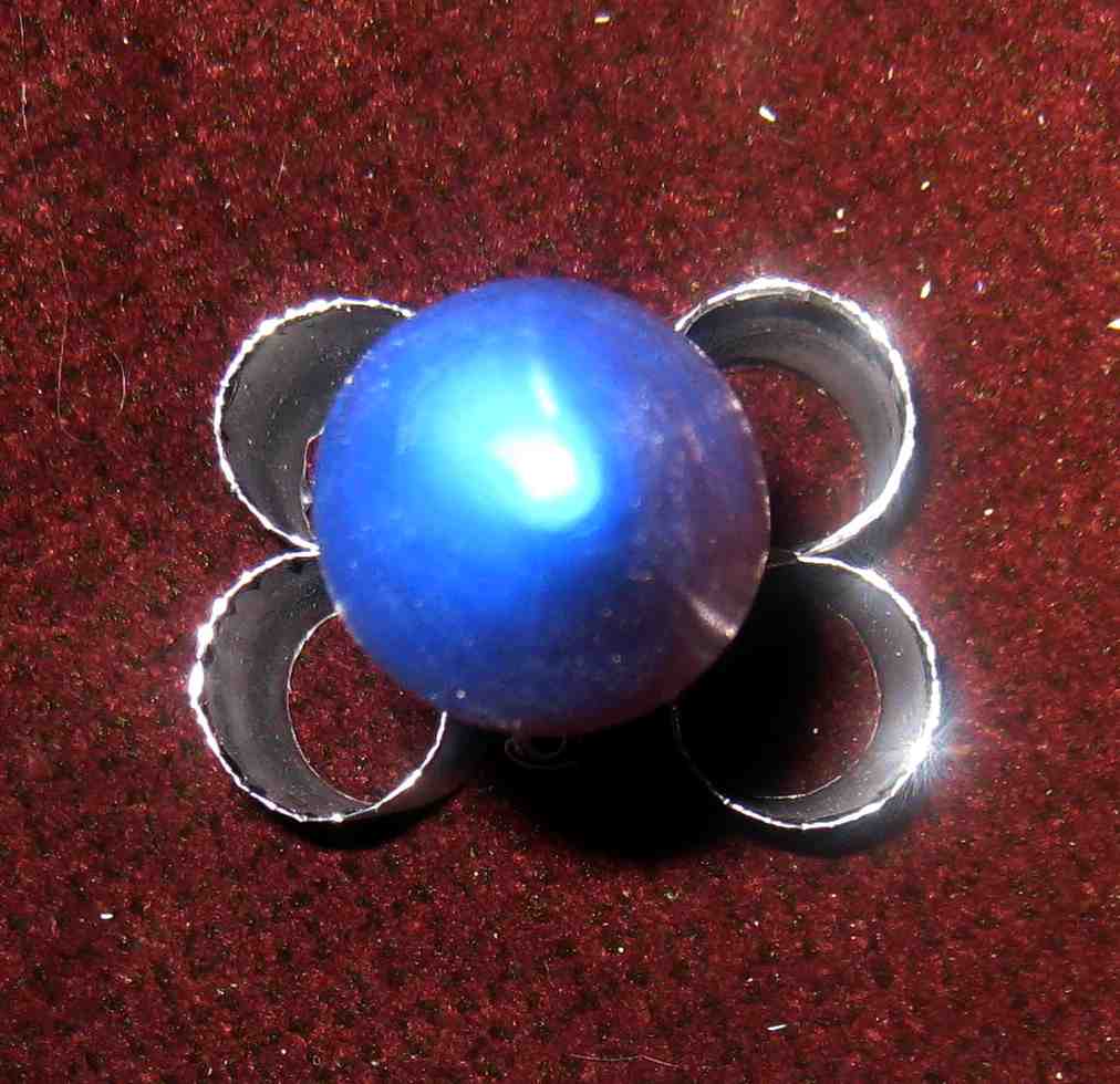
Color Scheme: All the pictures of the PLANET Uranus showed it to be a bluish color, so I figured I'd stay with this.
I primed the fuselage with Krylon White Primer, three coats, with light sanding between coats. This filled in the few defects I had left after the Filler. I used Krylon True Blue for the fuselage - I really like the color this gave, and I was happy with the finish here.
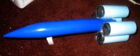
After painting the inside of the tube fins black, I took off the outer masking paper. I then rolled up paper INSIDE the tubes to mask the insides. This allowed me to "stack" the tubes, which actually made painting the outside easier. I had run out of primer, so I went directly to painting the outside of the tubes Blue Ocean Breeze. I did 3 coats, with a light sanding between coats. I liked this color as well. Although I hadn't thought it out ahead of time, I remember the three colors that were common for bathroom tiles in the 60s--- pastel yellow, pastel pink, and pastel blue. This looked pretty close to the pastel blue, connecting the planetary and Toilet Paper theme.
Moment of truth, what would happen when I peeled off the Mylar? Actually, I was quite pleased with the sharp edges. Pulling the tape off also raised some more "nap" off the cardboard tubes, exactly what I wanted to "rough it" for gluing.
As I had expected, despite the masking, there was a little bleeding of black and blue (no pun intended) at the edges of the tube fins. I used thin strips of silver Mylar tape to cover/accent the edges here and at the trailing end of the fuselage. As a USAFA grad, the silver and blue together got me right under the old squadron patch, as my Dad, a retired AF Navigator/Bombardier says. I wrapped the edges of the tape into the inside of the tube. Looking back, this gave the edge a bit of a rough look; I probably would just have put it on the OUTSIDE only, just up to the edge.
Now that this was finished, time to see how things fit together. I used medium CA to glue 4 tubes into two tube-fin pairs, placing the glue along one of the "naked" strips previously covered by Mylar. Laying the tubes flat gave me a good alignment. I then matched up the remaining strips on each tube pair with the strips on each side of the tail of the fuselage. They matched up pretty well, and the medium CA gave me enough time to make sure the alignment was perfect. I got a pretty solid joint (as I later proved in flight, but more on that later.) Fillets weren't needed, and the fit covered the "naked" areas.
I pried the Mylar tape out of the defect in the external coupler. This left a rougher edge.I glued in the launch lug.If I had to do it over, I would have pulled this off AFTER doing the filler step, but BEFORE painting, to get a better look.
Next question, where to attach the shock cord? If I attached it inside, it would get hit by the ejection charge fairly directly, and would also cause problem with sliding out the motor pod. Perhaps more importantly, if it came out the tail, the rocket would fall nose first. My launch site is about 3/4 grass, 1/4 asphalt. Invariably the better the finish on the rocket, the more likely it will land on the asphalt. Also, while the cardboard/masking tape/Elmer's Finish nose cone was holding the finish well, I could feel that it was still a little "soft" and didn't think it would hold up to a hard impact. Finally, I figured if I could get the rocket to descent in a horizontal position, the rocket body itself would be adding to the drag and slow it down.
With the rocket painted, the CG of the rocket body was right at the region of the external coupler. I threaded a needle with my Kevlar shock cord into the tube just above the coupler next to the launch lug, and pull about two feet out the after end of the fuselage. I then threaded a needle with the ENDS of a long loop of dental floss through a hole just BELOW the coupler and out the aft end of the fuselage. I then threaded ANOTHER loop of floss (loop 2) through this loop, and pulled loop 2 through the hole and out the tail, keeping the ENDS of loop 2 outside fuselage. I then used loop 2 to pull the shock cord BACK into the tail of the fuselage and back through the hole below the coupler (there probably is an easier way to do this, but this is what I came up with.) I then tied a tight "loop" of shock cord, running it just next to the launch lug, leaving about 1 1/2 feet of Kevlar loose. Yes, this loop DID run inside the rocket body, when the engine pod would slide in and out, but the cord was running longitudinally and wouldn't obstruct/catch on the pod. I did add a bit of thin CA to secure it.
Since I wasn't sure how well my hollow nose cone would hold up to the Estes engine ejection blast, I cut a bulkhead out of foam board and place it inside the body. It slid up to the "shoulder" that had been placed on the front of the body tube. Ejection blast would hit the bulkhead, but not the "formed" shape inside of the nose cone. Instead of gluing it into place, I placed a length of Kevlar on this in case I needed to pull it out later (such as to add nose weight), and left that loose.
Engine Pod: I originally planned to use a length of BT20 as an engine mount AND pod. However, after building it, I discovered I wanted more room for my parachute and streamer. I used a BT20 for an engine mount. I then wrapped the end of a BT5 with electrical tape until it just fit inside the BT20. The BT5 acted as BOTH an engine block AND a duct to direct the ejection force to the front of the body, where it hit the bulkhead. I used foamboard to cut adapter rings for the BT20 at the tail and the BT5 at the front of the body. These were sanded to slide loosely, but hopefully the front one would be tight enough to seal the ejection charges away from the chute and streamer. Looking back, I probably should have used two adapter rings up front, as a little bit of ejection charge snuck around the front ring and slightly charred the streamer.
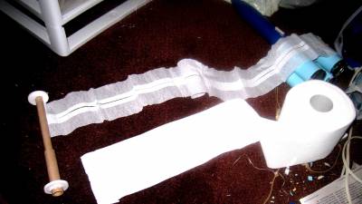
I had initially planned on a long white "simulated TP" streamer to recover the rocket (in keeping with the theme). However, early on it was clear that given the weight of the rocket a streamer would never safely slow the rocket AND the engine pod. Also, again I knew the nose cone was a little bit "soft" and wanted to cushion the landing of the body as much as possible. My solution had two parts. First, allow the engine pod to completely separate from the body of the rocket, so the two descend separately. This reduced the weight of the body of the rocket (with the soft cone). If I needed nose weight, I could add it to the front of the pod, rather than the body. This is a NICE trick with rear ejection boost gliders, by the way. You can adjust your CG by adding weight to the front of the ejection pod, without affecting the weight or CG of the glider itself. Then I could use my white streamer to safely recover the engine pod (which wasn't really very delicate and was not that heavy), and a parachute to recover the body. The shock cord for the body was attached to OUTSIDE of the fuselage at the CG, thus the body descended horizontally under the chute.
I used two pieces of white crepe paper to create the streamer for the body tube. I attached them side by side with silver Mylar tape. I then accordion folded this into squares to simulate toilet paper sheets. The silver tape showed on one side, which I thought would be easy to see (on the off chance this bird flew outside my launch site-- yeah, right.) The other side was straight white, which looked like, well, toilet paper. While for the real theme this would be "rolled" around the engine pod "spindle", my experience is that this is unlikely to "unroll" in flight during descent. Therefore I stayed with the accordion fold. I used a length 10 times width, according to Stine's book of optimal streamer length, then added a couple of inches to give me space to attach it to the BT5 section of the pod.
I used a couple of thick rubber bands to link the parachute to the Kevlar shock cord attached to the mid section of the exterior body of the rocket.
Note: Originally I used Tim Van Milligan's Model Rocket Design & Construction book to make two semispherical parachutes, then "ironed" the two together side to side. The idea was to create a parachute with a "cleft" down the middle, the so called "glute chute." (For those who have actually intentionally fallen out of perfectly good aircraft, there is a parachute malfunction called a "Mae West" that looks somewhat similar.) However, while the parachute looked good, the "glute chute" didn't pack very tightly, and even reducing the engine pod diameter from BT20 to BT5 didn't give me enough room to actually use this. I made an 8-line 12-inch chute out of a green garbage bag (okay, was getting tired of the theme at this point.)
 Flight
Moment of truth arrived. Would this work?
First "gotcha" was the prep. The overhanging 4 tube fins may (or may not) look cool. They do however obstruct access to the tail of the body. This is bad enough when all you have to do is stuff an engine in, but when you have to shove in the entire engine pod with the accordion streamer AND the parachute up the rear, those overhanging tubes REALLY get in the way.
Anyway, seemed like a C6-3 engine would probably be a good start for this.
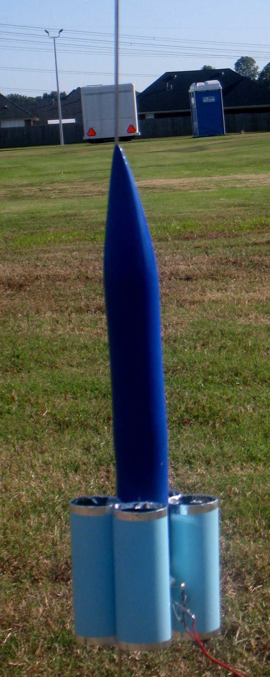
Loaded it up on a nearly windless sunny day. Crossed my fingers. Fired. Boost was arced to the left (not sure if this was due to some uneven-ness of the fins.) Made it to roughly 150 feet, at apogee was traveling nearly horizontal. Ejection was at or near apogee.
Recovery
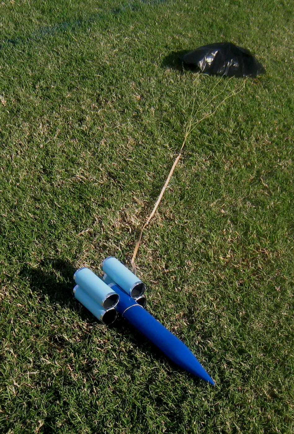
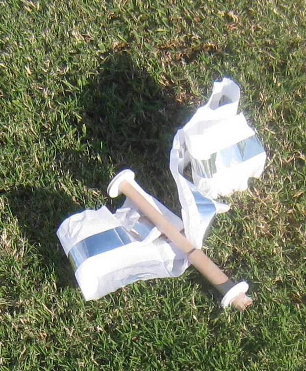
Perfect separation of pod and body. Streamer extended nicely and at 36 inches long, 3 inches wide, white and silver, was quite visible. Chute also opened well. Rocket was far away at this point, but the descent was either horizontal or slightly tail down (just what I wanted, to protect that nose!) Pod and body landed about 100 yards from pad, about 10 yards apart, on the grass. Absolutely no damage from the fall. The white streamer was very slightly singed.

Had I been smart, I would have counted my blessings and put the rocket on the shelf at this point. However, I'm not smart. I decided to try it again. On flight two the engine pod apparently caught on something (may have been packed too tight.) Probably my combined two tubes were not as smooth internally as a single standard store-bought tube would have been. Negative ejection. Lawn dart. Not sure any nose cone would have come thought this unscathed, but my (five coats of filler, multiple hours of sanding, multiple coats of paint - whimper whimper) nose cone accordioned. Not fixable.
Summary
Pros:
- I had fun, probably as much writing the background story as building and flying the rocket.
- The paper/masking tape/filler nose cone came out well, and I think I may use this again for rear ejection models (but will start with a REAL body tube!) Also particularly nice for a large but light nose cone. The nose finishes well and looks great
- Rear Ejection worked well. Downsizing the central "duct" from BT20 to BT5 works great and gives you extra space for your recovery device(s). The BT5 also functions as an engine block. No wadding required. . Again, you can use the long engine pod to add any needed weight far forward on the engine pod (and thus anterior on the rocket in boost phase) to bring the CG forward on boost phase without adding weight to the glider at separation.
- Separating the pod from the body allows the more delicate body to descend slower.
- The Mylar Mask Strips worked well in allowing me to pre-finish and pre-paint parts prior to assembly, but still allow a strong joint. Wondering if this might work on an Estes Outlander that I have yet to build. Suggestions would be welcome.
- External shock cord attachment at CG allowed model to descend horizontally. That a horizontal descent position adds more drag on descent is already well known. However it also allowed me to avoid the soft nose hitting ground, which would be the normal orientation for a rear-ejection model. This technique may be useful in rockets where certain parts of more fragile than others. You can adjust the attachment position to make it less likely these parts will directly impact the ground on recovery.
- Stayed with Planet Uranus/Toilet Paper Theme
- Parts were cheap (until you think of the time it takes for extra finishing)
- It WORKED! (well, at least once.)
Cons:
- Paper/Tape/Filler nose cone is slightly soft. It requires a bulkhead to protect it from ejection charge and should not be allowed to directly hit the ground on descent (especially not ballistically.)
- External Shock Cord is a bit difficult to stuff into the engine pod as you stuff the engine pod into the tail of the body.
- Separating pod from body on recovery means you must track both (but the pod falls pretty fast, so shouldn't drift much.)
- I couldn't leave well enough alone and stop with one flight.
- For some reason the white paper streamer kept catching on my heel.
Related External Links


 |
 |
Roger Smith (August 15, 2011)
There's a discussion of this review in The Rocketry Forum.
Sponsored Ads


|
|
Hans "Chris" Michielssen (August 15, 2011)
Great review and "back" story of the rocket. (But, you didn't use the word probe once!)
Certainly a true scratch build. Anybody who forms a nose cone out of a body tube is okay by me.
thanks for the laugh and great build.