Scratch Triactive Original Design / Scratch Built
Scratch - Triactive {Scratch}
Contributed by Peter Clay
| Manufacturer: | Scratch |
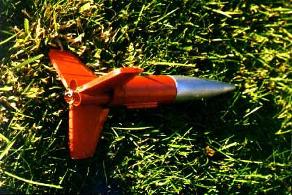
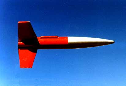
Cluster model for A3-4T and A10-3T motors A cluster of three 13mm tubes, compressed slightly, fits in the 29mm HPR motor mount tube. This in turn requires a little packing to fit neatly in a BT-55 or BT-56. To accomplish this, I cut strips of Kraft paper (like grocery bags), applied glue to one side, and wrapped it like tape until it fit neatly. A short piece (5/8" approx, the 15mm section in the drawing) of body tube serves as a stop ring.
My nose cone was salvaged from an old rocket very similar to the 56-based RTF's. After cutting the cone-shaped bottom end off the nose cone, I found that the 29mm tube fit neatly inside the remaining shoulder. (you may need to build it up or sand to fit.) ÝI put a plywood cap on the tube forward end with a screw eye in the center facing in. Cap and screw eye were secured with epoxy. Opposite end of tube was built up with Kraft paper as described above. Then I pushed the 29mm tube as far into the nose cone as it would go, fitted this into the BT-55, and when I was happy with the fit, I epoxied everything together. This arrangement moves the parachute compartment well up into the nose cone, making the rocket at least 4" shorter than it would have to be otherwise. (After flying it, I'm thinking of extending it for better stability.) Nose weight (clay) was in place for the previous design and, judging from the first flight, is necessary. The rocket was marginally stable at takeoff and straightened out pretty quickly. The diagram below doesn't show the screw eye in the front. Instead, I've shown the shock cord pushed through the hole in the cap and tied in a knot. I'm sure that would work. In real life I used a screw eye. Live with it.
The shock cord consists of: 6" of 125# Kevlar (red); a fisherman's swivel; and 30" of nylon braided plumbline(green). This worked. The 12" plastic parachute is attached to either end of the inline swivel using a snap swivel of its own. The bulkhead at the front end of the coupler was an adventure. It is cut from plywood, fits on the end of the 29mm tube, but inside my Kraft paper buildup. It has three holes 8mm diameter to allow ejection charge gasses to pass. It has two tiny holes near the center to anchor the Kevlar thread. Before assembly the Kevlar was looped through those holes and tied. The knot, under the disk, is covered with epoxy. The holes in the disk are rotated 60 degrees from the three MMTs, so that the ejection charges don't blow straight at the holes. Free to slide on the Kevlar is another plywood disk with a small hole in the center which fit easily in the BT-55, but is much too large to fit in the 29mm tube. It fills the role of recovery wadding, not only protecting the parachute from heat, but preventing it from being packed up into the nose cone by the ejection charge. This worked. There was not a hint of heat damage on the parachute or upper portion of shock cord. When packed, as much as possible of the Kevlar should be forward of the plywood disk; the last inch or so will be between the perforated bulkhead and the disk. Fins are made from artist's foam core board, which is about 3/16" thick. To wedge the leading edge, I scored each fin, both sides, with a ruler and Xacto, about 10mm (3/8") from the leading edge. I cut away and removed the foam from this portion, folded the edges toward each other, and glued them together, holding them with masking tape until the glue dried.
For motor retention, I first installed thrust rings made from cut pieces of a spent engine. Then I epoxied a threaded rod -- a #4-48 x 3/4" bolt with the head cut off -- into the gap between the three motor tubes. With the engines in place, I thread a nut onto the rod and it holds all three motors. Triactive first flew Sept. 6, 1999 at Tom McCall School in Forest Grove, OR., using 3x A3-4T.
|
|
Sponsored Ads


 |
 |