| Manufacturer: | Scratch |
Having always wanted to add functionality to my rockets, I decided that adding a camera would be a great start. I scoured the internet via Rocketry Online, as well as directing my browser to any camera link mentioned in RMR. It seemed a lot of rocketeers had used the circuit on Rob Nee's AYUCR page. It seemed simple enough, so I was off to the races. I had a Minolta Freedom 50 camera that my wife had discarded and replaced because she was having problems with it. It needed minor attention and soon found itself on the operating table. What I had failed to realize was that this camera had a mechanical shutter button. DOH! I had already started the circuit and was having problems getting it to work right. (note: Rob was very helpful via several email exchanges) In my searching for another way to operate the camera, I stumbled upon a servo testing circuit that seemed to be what I was after. So it was back to the electronics store for more components. I was going to use a servo to somehow press the shutter button on my camera......
Then a couple of months ago, Ray Dunakin posted to the ROL forums that he had just posted some new pictures to his website. After seeing some of the best inflight pictures I have ever seen, I fired off an email to him to find out how he operated his camera. He replied in short time with a nice description and a picture of his "capsule". In his note he mentioned that he used a servo and cam to drive his camera. From the picture that he sent me, the setup seemed pretty straight forward.
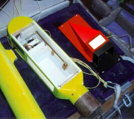
Ray Dunakin's Camera "capsule"
In scrounging around my house for the materials to build the pod, I decided that for my 1st attempt I would not use the mirror for downward boost shots, but instead have the camera looking straight out upon boost and face down upon descent. This was due to the fact that I had a little over a week till our next club launch and I wanted it to be functional by then.
CONSTRUCTION
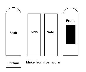
The capsule is made of foam core board, plywood, a coupler the size of the booster, some foam, and surplus 3.9" BT . I used 5min. epoxy for my glue joints with CA here and there. I also opted to glass the entire pod.
The first step is to measure your camera dimensions and make sure that you calculate for the side pieces. You want to have a snug fit to keep the camera from shifting, yet leave a little room on the right side for the lever you will make for the shutter (approx 1/4-1/2"). What you are doing is making a boxed rectangle into which your camera, servo, batteries, and any circuits you choose will fit. See diagram below. It goes together supprisingly fast. For the top of the pod, cut a piece (semicircle) of body tube of the appropriate depth and glue to the back and sides at the top of the camera compartment. Cut out an area of the front piece to allow for the lens and light meter to be fully exposed.
I glued a 1" piece of BT to the bottom section, then used 3/4" foam to form my transition. The coupler was attached using a piece of allthread to facilitate my altimeter. You can skip that and glue the coupler inside the 1" BT if you want.
SERVO INSTALLATION
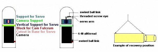
What you are trying to accomplish is to have the servo arm rotate 360 degrees continually. You will have to take the servo apart and remove the "stops" which prevent this. NOTE: While you're in there, if you choose the simpler method of powering the servo, remove circuit board and solder black and red wires directly to the motor. Run these wires out of the servo case when you put it back together.
With your camera in position in the pod, glue a piece of plywood that will run from side to side just in front of the camera. Make sure that you can easily install and remove the camera before you glue it in (see diagram). You will also need to make a sturdy base for the servo. I traced a line around the servo and cut out the hole that will support the base of the servo. I also glued 2 vertical braces that extend to the top of the servo. You can screw a piece of wood to the top of the 2 supports or use velcro to secure the servo in place. Cut a piece of hardwood block or laminate 2 pieces of plywood to make the block or the cam fulcrum to be screwed into. I used basic radio control items for the fulcrum and lever. The lever that connects the cam to the fulcrum is 4-40 allthread that is used for push rods. Both the fulcrum and connecter to the servo arm are plastic swivel ball links with brass inserts and threaded ends. I used a 4-40 threaded screw eye to connect the cam setup to the lever. Use a 4-40 nut on the allthread to retain the screw eye.
Depending on your setup, you may have to build up the area where the lever makes contact with the shutter button.
FLIGHT PREPARATION
I secured the front piece to the unit with electrical tape. On future pods I will use some strips of plywood or hardwood blocks around the perimeter to facilitate small screws. I used foam padding in the pod and where the front makes contact with the camera to make things secure.
On my first flight, the servo was driven by the circuit that I mentioned earlier. It used potentiometers which enabled me to adjust the rotation of the servo. It worked well, but when trying to add a timer to it to delay the activation till apogee, I must have fried the electronics in the servo, because it no longer would receive the pulses from the circuit. So, in another email to Ray, I asked him how he drove his servo. He said he used 2 "AA" batteries wired directly to the servo motor. When I read this, I laughed almost convulsively at all of the hours of head scratching, fiddling and 10+ email exchanges with Doug Sams, trying to get my fancy circuit to work right. Well, the second outing used the 2 "AA" batteries and everything worked fine. It gives the servo very close to 1 rotation per second, which is what I was looking for. YMMV. Use whatever method of servo operation your abilities allow. To start the servo, you can either flip a switch prior to launch, or make a switch that is actuated at liftoff. Don't be afraid to ask for help. I met some very nice rocket folk in my journey, who were very willing to help me out.
PARTS LIST
| Item | Price est. |
| 1 standard servo | $12.00 |
| 1 sheet foamcore board | $ 5.00 |
| 2 plastic swivel ball links | $ 4.00 |
| 1 length 4-40 allthread | $ 3.00 |
| screw eye 4-40 thread (pkg) | $ 1.50 |
| 1/8" aircraft plywood | $ 4.00 |
| 3/4" foam | varies |
| 4" bodytube | scrap |
| coupler (varies) | $ 2.50 |
| bulkhead | $ 2.00 |
| camera | varies |
| misc. wire, batteries, switches | $ 4.00 |
| Total (less camera, foam) | $38.00* |
* You may have some of this stuff lying around or use substitutes
INTO ACTION
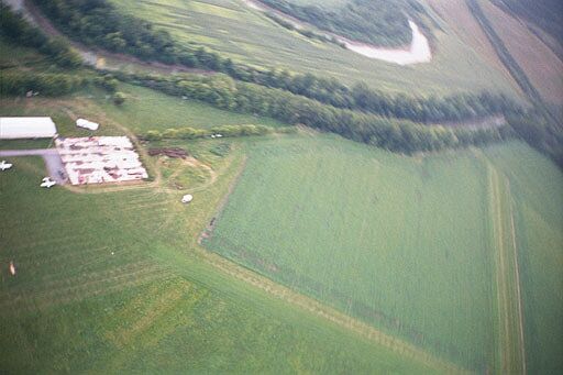
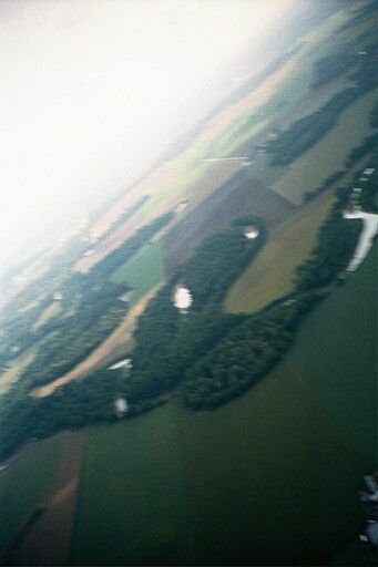
The following were taken on 8-5-00 at Mr. Weigand's hay farm near Baldwinsville, NY
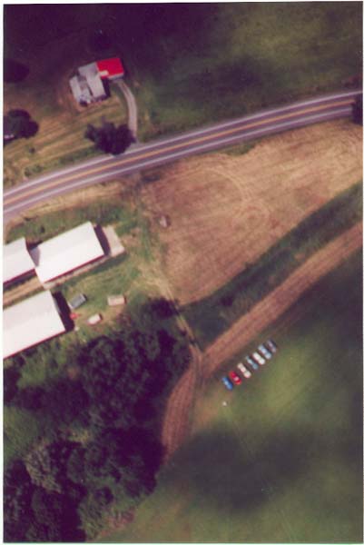
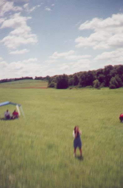
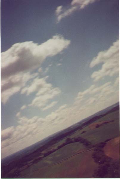
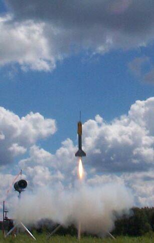
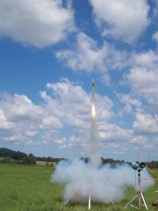
Camera payload boosts on an Aerotech G64!
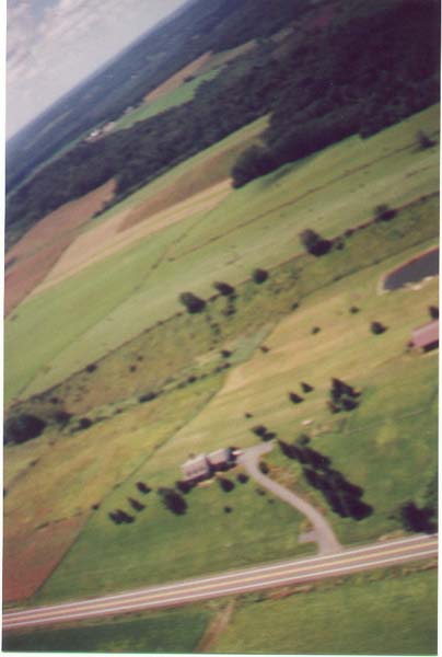
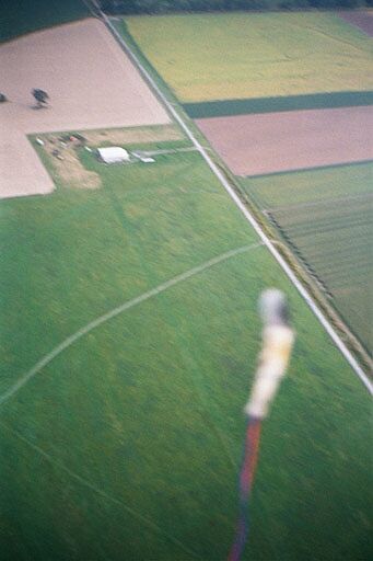
The following were taken on 9-9-00 in Geneseo, NY. Boost provided by an Aerotech H123
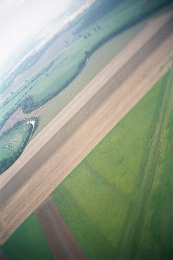
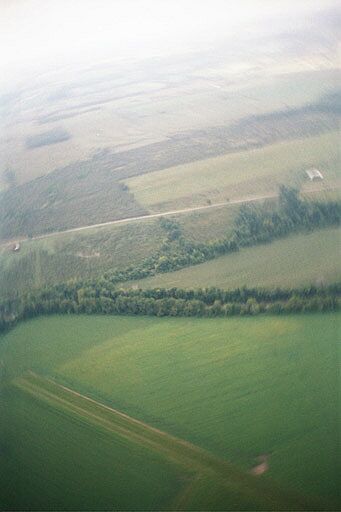
The quality is at best fair-good. I plan on doing a couple of things in the future to achieve better results. One is to use a Rocketman or X-form chute for more stable descent, and also get a better camera. I've heard great things about the Olympus Stylus. When finances permit, I think I'll try one.
Thanks for checking it out. I welcome any comments, suggestions, and questions you may have.
Ned Nassif
special thanks to Ray Dunakin, Doug Sams, John DeMar, Rich Pitzeruse and Tom Biasi!
Sponsored Ads


 |
 |