Scratch My Mind's Eye Original Design / Scratch Built
Scratch - My Mind's Eye {Scratch}
Contributed by Douglas Gerrard
| Manufacturer: | Scratch |
Note: This is a slightly modified version of all the information that Doug has produced for his Level 3 project. Visit his site to read the additional information and enjoy additional pictures.
 Introduction
I entered high power rocketry in 1988 for the sole purpose to fly camera rockets. I have been flying model rockets since 1973 but the class C motors are just not adequate to provide the necessary power to achieve the altitude required for a camera to take quality pictures. I have flown dozens of different kinds of cameras from a variety of rockets and configurations. I have flown 110, 35 mm, 8 mm movie, video, and even a large format (4" x 5") camera, but by far the most common camera I fly is the 35mm. 35 mm cameras have fast film advance rates (up to 2 ½ frames per second), very fast shutter speeds (1/2000th second), and the film is large enough to get great pictures when enlarging the print. Anymore, I don't fly a rocket without a camera on board.
This certification level 3 project provided me with the opportunity to take photographs with a unique perspective that is just not available with level 2 rockets. The larger diameter rocket, payload weight available, and altitude achieved allowed me to achieve many of my goals. The general goals of this project are:
- Design and build a large rocket capable of lifting multiple camera payloads.
- Fly the rocket with an M motor safely and achieve my level 3 certification.
- Take photographs of specific target objects.
- Recover the rocket and cameras intact.
Specific Design Objectives
 I did not want a complex rocket.
The rocket design is a straightforward, single stage rocket. Only the payload
is complex. However, there are some specific photographs that I wanted to
achieve with this project. The specific design objectives are described here.
I did not want a complex rocket.
The rocket design is a straightforward, single stage rocket. Only the payload
is complex. However, there are some specific photographs that I wanted to
achieve with this project. The specific design objectives are described here.
- One photograph that I have always wanted to get was a profile shot of the
booster descending on its parachute with the horizon in the background. I have
tried to get this by pointing a camera out the side of the payload section, but
the odds of getting the booster in the view of the camera is very small. How
can such a photograph be guaranteed? By placing the payload section above the
booster, having the payload section descend faster than the booster, and
photographing 360° around the payload section of course. This required a
set of eight (8) cameras mounted at equal spacing around the payload section
that take their pictures simultaneously as the rocket and payload descend on
their parachutes. Since the booster section deploys its parachute at a lower
altitude than the payload section does, this design will also require the
payload section to descend faster than the booster to overtake the booster and
pass it as they descend to the ground. These cameras are numbered 1 through 8.
- I also want to photograph the rocket as it ascends to apogee. This view
covers 360° below the rocket. To achieve this, a pair of 35-mm SLR cameras
are mounted so their angle of view is 180° to each other looking out
perpendicular to the rocket. The view is then reflected down the side of the
rocket via a first surface mirror and the cameras are triggered simultaneously
from the same timing circuit. The angle of the mirror is such that each camera
should be able to see part of the rocket body and fins. In this way the
photographs will overlap slightly, nearly doubling the coverage from one
camera. The two photographs can be joined together to provide 360°
coverage below the rocket. These two cameras are activated at take-off and are
numbered 9 and 10.
- One camera is specifically designed to photograph the booster falling away
at separation. One 35-mm SLR camera is mounted in the base of the payload
section looking straight down into the booster. This camera is activated at
separation to capture the booster falling away and continue to photograph the
booster as it descends below the payload section. This camera has a wide-angle
lens for general aerial photography and is numbered 11.
- The payload section must be stable, even though it is not powered, to
ensure photographs are taken of the booster falling away. If the payload
section is unstable it might tumble and the booster would quickly move out of
the camera's field of view. Since the payload section should still be climbing
when the booster separates, the stability of the payload section ensures that
the payload section is above the booster when its parachute is deployed and the
cameras remain looking at the booster.
- And finally, these payloads are carried to an altitude of approximately 4,000 feet.
With these design objectives defined, I designed the rocket to meet these 5 criteria. What follows is my level 3 certification project.
Description of the Flight
 There is nothing special about
the sequence of events for the rocket flight. After the motor burns, there is a
coasting phase to apogee where the parachutes are deployed. However, it is
slightly unusual in that the booster separates from the payload section
approximately two seconds before apogee to deploy the booster's parachute and
the payload section continues to climb to apogee where its parachute is
deployed.
There is nothing special about
the sequence of events for the rocket flight. After the motor burns, there is a
coasting phase to apogee where the parachutes are deployed. However, it is
slightly unusual in that the booster separates from the payload section
approximately two seconds before apogee to deploy the booster's parachute and
the payload section continues to climb to apogee where its parachute is
deployed.
Sequentially, at takeoff cameras 9 and 10 take pictures every 0.5 seconds until motor burnout and then one picture every 1.5 seconds to booster separation. The booster separates approximately 2 seconds before apogee when cameras 9 through 11 take about 4 pictures at a rate of 2 frames per second. At the end of these pictures, with the payload section close to apogee, the payload section deploys its parachute. There is about a 10 second delay for the payload section to settle down then all 11 cameras take pictures until they run out of film on descent of the parachute.
Here is a detailed description of the sequence of events for each set of cameras.
Cameras 1 through 8
 Cameras 1 through 8 described
above start taking pictures 10 seconds after separation. This delay is to allow
the payload section to settle down from the parachute being deployed. All eight
cameras are activated simultaneously every 5 seconds from two 4-pole relays.
Cameras 1 through 8 described
above start taking pictures 10 seconds after separation. This delay is to allow
the payload section to settle down from the parachute being deployed. All eight
cameras are activated simultaneously every 5 seconds from two 4-pole relays.
Cameras 9 10
Cameras 9 10 start taking pictures at a rate of approximately one picture every 0.5 seconds from takeoff through motor burnout, then one picture every 1.5 seconds to booster separation (~24 shots). The change in the rate of pictures being taken is desired because early in the flight, during the motor burn, the rocket's altitude is changing very fast and it is still close to the ground. After the motor burn, the altitude is higher and the rocket speed is decreasing. Since an object in the camera's view is not changing as fast, fewer pictures are required. At separation, the cameras shoot in continuous mode for approximately two seconds (~4 pictures). Then there is a delay of about 10 seconds to allow the parachute to open and settle down. Then the remainder of the roll of film is shot at a rate of one picture every 5 seconds.
Camera 11
 This camera starts taking
pictures at booster separation continuously for approximately two seconds (~4
pictures) to capture the booster falling away. Again, there is a delay of about
10 seconds to allow the parachute to open and settle down and the remainder of
the roll of film is shot at one picture every few seconds.
This camera starts taking
pictures at booster separation continuously for approximately two seconds (~4
pictures) to capture the booster falling away. Again, there is a delay of about
10 seconds to allow the parachute to open and settle down and the remainder of
the roll of film is shot at one picture every few seconds.
Project Description
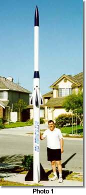
The rocket is shown in Photo 1. Individual sections of the rocket are
further described in the Structural Design Considerations section. The details
of the overall rocket are:
Height: |
17' 6" |
Weight: |
110 pounds |
Diameter: |
7.7" reduced to 5.6" |
Parachutes: |
2 Rocketman® R18C parachutes |
Payloads: |
8 35-mm point shoot cameras 3 35-mm SLR cameras 2 Adapt® PST941 timers 2 Black Sky® ALTACC |
Motor: |
1 M1939 Aerotech® Reloadable |
The rocket has a 7-foot long booster made from LOC® BT-7.51 tubing with a 98 mm motor mount. Immediately above the booster is a 3-foot payload section where the cameras are mounted. The payload section has cowlings and fins to stabilize it. Although it may look like a second stage, it is not powered.
Above the payload section is a reducer that tapers the rocket down to LOC® BT-5.38 tubing. This is where the payload’s parachute is located. The nose cone is also LOC's, a PNC-5.38L which is weighted for stability of the payload section.
 Each camera uses a roll of 36
pictures but usually 37 photographs can be taken from such a roll. On one
flight a total of 407 pictures are taken from eleven high quality cameras.
Each camera uses a roll of 36
pictures but usually 37 photographs can be taken from such a roll. On one
flight a total of 407 pictures are taken from eleven high quality cameras.
The expression "My Mind's Eye" has been described by psychiatrists as "mental images, pictures, or sensations in your imagination". This is an excellent description of this project. The design objectives were created based on ideas of what I wanted to photograph and then the rocket was designed to meet those objectives.
Structural Design Considerations
Body Tubes
The booster of the rocket and the payload section are constructed from LOC® BT-7.51 body tubes. The diameter was selected to accommodate the cameras in the payload section. Its length is 7 feet so that the fins will still be in focus for the cameras that look down the side of the rocket and to increase overall stability. All body tubes are covered with fiberglass and epoxy for re-enforcement. The weight of the fiberglass and the number of layers are different for different areas of the rocket. The upper section of the booster has two layers of 3-ounce fiberglass.
There is a removable electronics bay in the booster that contains the Adept® Rocketry Timer and the Black Sky® ALTACC for the booster ejection charge. The timer is the primary circuit and the accelerometer is the backup circuit. Two are used for reliability and both use an electric match that ignites the same ejection charge.
 The entire rocket is covered with
fiberglass, epoxy, two coats of white epoxy primer paint, and several coats of
finishing paint. Two brass machined rail guides are attached with wood screws
to the two 1 inch centering rings at the end of the motor mount tube.
The entire rocket is covered with
fiberglass, epoxy, two coats of white epoxy primer paint, and several coats of
finishing paint. Two brass machined rail guides are attached with wood screws
to the two 1 inch centering rings at the end of the motor mount tube.
Motor Mount Assembly
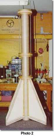
The motor mount is constructed from LOC's heavy-duty thick walled (0.090") 98-mm motor mount tube. Photo 2 is a diagram of the motor mount configuration. It uses two motor tubes connected by a centering ring. Two 5/16th inch closed eyebolts are attached to the all-thread that extend down to the fin unit centering ring. The all-thread has nuts, washers, and lock-washers on both sides of every centering ring.
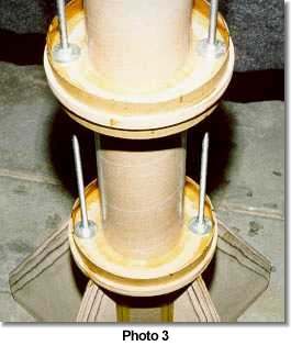
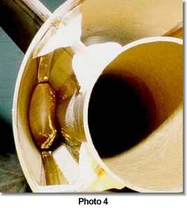
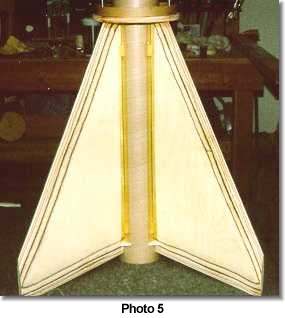
The fins and centering rings (Photo 3) all have internal fillets as shown in Photo 4. Having both internal as well as external fillets increases the strength of the joint without having unsightly, massive external fillets alone. The centering rings are made from ½-inch thick, oak plywood. Two centering rings are used at each end of the motor mount tube (1 inch thick). The fins, shown in Photo 5, were constructed from 1/8th inch G-10 fiberglass in the core and laminated with 3/16th inch plywood on each side and the leading and trailing edges were tapered.
The Reducer
The reducer is made from solid hard balsa from LOC custom engineering. It is specifically designed to have full diameter length shoulders for both the upper and lower body tubes. The bottom of the reducer has a ¼ inch plywood plate that is epoxied to the base of the reducer and six ¼ inch by 6" long lag bolts to secure the plate. The purpose of the plate is to secure two ¼ inch T-nuts for two bolts that will secure the mount for cameras 1 through 8. Attached to the ¼ inch plate is another ½ inch thick oak plywood plate that also has T-nuts used to secure the camera payloads to the reducer.
The top of the reducer has four 12" pieces of ¼ inch all-thread, which stick out of the top of the reducer about 3/4 inch to secure the upper body tube. The upper body tube is used for the payload’s parachute compartment and has a 1/8th inch fiberglass plate sandwiched between two 3/16th inch thick plywood plates and epoxied into the BT-5.38 body tube. This plate has two 5/16th inch closed loop eyebolts for the payload recovery and is bolted to the reducer. A hole has been drilled through the reducer to pass electrical wires for the upper ejection charge located at the top of the reducer. The reducer is covered with 3 ounce fiberglass and epoxy except for the shoulders.
Recovery Design
The most likely failure of the flight is with the recovery. This design incorporates several ideas to reduce the chance of recovery failure.
- There are two parachutes (Rocketman® R18C), one for the booster and one for the payload section, to prevent any damage the rocket would suffer by having one section slam against the other if only one parachute were used.
- Every eyebolt in the recovery design is a 5/16th inch closed loop eyebolt with a working load of 900 pounds.
- This design uses nomex® in both the booster and the payload section to ensure that the parachutes are protected as well as using a deployment bag.
- The parachutes are attached by tubular nylon rope with the ends secured.
- Below the parachutes, two flat tubular nylon ropes are used for added safety. Both are coated with black electrical tape to prevent the hot ejection gasses from burning and weakening the ropes.
Nose Cone
The nose cone is the PNC-5.38L from LOC. The nose cone is epoxied to a 30 inch piece of BT-5.38 body tube. A regular body tube coupler is used to attach this section to the payload section. There is about 10 pounds of weight added to the nose cone to increase the stability of the payload section as well as the entire rocket. The parachute is attached to the weight in the nose cone via a 5/16th inch steel all-thread rod, and the weight is firmly attached to the nose cone by plaster, which also adds additional weight.
The coupler is reinforced with four 1 inch wide pieces of ½ inch thick oak plywood. The body tube is covered with fiberglass that extends above the shoulder of the nose cone to further increase the strength of this section.
Launch Pad
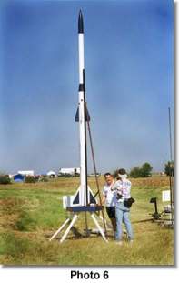
The launch pad (Photo 6) is of my own design and is truly a launch "pad". It is basically a pentagon shaped table with reinforced legs that the rocket sits on. Of course there is a 7- inch diameter hole in the middle of the table for the blast of the motor. The legs are angled at 45º for greater stability and to attach support brackets for the rail. The height of the table is over 3 feet from the ground to allow clearance for the blast of the motor. The rocket is guided by a 12 foot long Black Sky® ProRail. The rail is secured at the table by a hinge as well as at the legs. The launch pad is staked into the ground at the legs to ensure it will not tip over while loading the rocket onto the pad or during launch.
Redundancy, Reliability, and Recoverability
This design incorporates redundancy, reliability, and recoverability in many different ways to ensure the goals of the project are met. These include:
- No clustering or staging was used, to reduce the risk of failure.
- The weight of the rocket ensures that the rocket will not go supersonic.
- The rocket is launched at a 0º angle.
- Dual ejection charge circuits for both booster and payload sections.
- Through-the-wall fin design is used.
- Multiple internal fillets are used.
- Fiberglass covering increases the strength and reduces the chance of structural failure.
- Only closed eyebolts are used in the recovery design to increase strength.
- No elastic shock cord is used. Only nylon rope for the recovery system is used.
- Booster parachute is attached to all-threads that extend to the fins and motor mount.
- All-threads extend through the payload section to secure the payloads to the recovery parachute.
- Both parachutes use a piece of nomex® for protection from the ejection charge.
- A deployment bag is used to reduce the shock to the rocket when the parachute opens.
 Payload Design
Considerations
Payload Design
Considerations
Camera Compartment
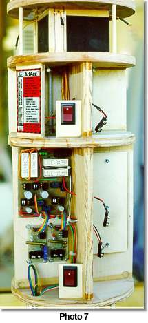
The camera compartment is located in the payload section immediately above the booster but below the reducer. Photo 7 shows details of the payload section. All plates are made from ½ inch thick oak plywood and there are ¼ inch holes drilled through each plate for all-thread to connect the entire assembly together and to the T-nuts in the plates on the bottom of the reducer.
Cameras 1 through 8
The top part of the payload section is for cameras 1 through 8. Two layers hold 4 cameras at 90º to each other and then the layers are skewed 45º to each other. The design needed to hold the cameras at the appropriate angle is simple yet challenging. The back of each camera rests next to a ¼ inch piece of plywood that has a 1/16th inch thick piece of foam padding attached to it. In front of the camera is a vertical piece of 3/16th inch wooden dowel rod that passes between the two plates. The padding and the dowel rod provide a nice friction fit used to hold the camera at one end. The other end of the camera is held secured by a ¾ inch long ¼ - 20 flat-head screw from the bottom of the plate. This design is challenging since the four cameras had to be mounted at 90º to each other inside of a 7-½ inch body tube. The clearance between each camera is about ¼ inch.
Electronics Compartment
Below the point and shoot cameras is the timing circuit and the ejection charge circuits compartment. One cross member is made from ¼ inch plywood and the other is from ½ inch oak plywood. On both sides of the ½ inch plates are 1/8th inch thick fiberglass pieces epoxied to the plate to reinforce where the all-thread bolts them together.
Cameras 9 and 10
 Below the electronics is the
compartment for cameras 9 and 10. Due to the size of the two SLR cameras, four
smaller supports are used to connect this section to the rest of the payload
section. To install a camera the lens of the camera must be removed and the
camera is slid into its holder and then the lens reinstalled. The angle of
cameras 9 or 10 is 40º, versus 45º from the axis of the all-threads
like the point and shoot cameras. The cameras are secured by a ¾ inch
¼ - 20 flat-head screw from the bottom of the plate.
Below the electronics is the
compartment for cameras 9 and 10. Due to the size of the two SLR cameras, four
smaller supports are used to connect this section to the rest of the payload
section. To install a camera the lens of the camera must be removed and the
camera is slid into its holder and then the lens reinstalled. The angle of
cameras 9 or 10 is 40º, versus 45º from the axis of the all-threads
like the point and shoot cameras. The cameras are secured by a ¾ inch
¼ - 20 flat-head screw from the bottom of the plate.
Camera 11
The coupler is at the bottom of the payload section that holds camera 11. This coupler is the structural support for the payload section in the booster. It is reinforced by epoxying another coupler inside the original coupler. Six ½ inch thick oak strips run the length of the coupler. This double wall design and the reinforcement strips are necessary for strength and to protect the payload section upon landing. This coupler also contains the switches used to control the cameras. Camera 11 is mounted lens down, looking into the booster.
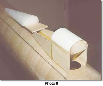
Cowling
Photo 8 shows the cowling that is used to protect the mirrors on the outside of the body of the rocket. The angle of the mirror is 50.5º to achieve the desired angle of view. The frame of the cowling is constructed from 3/16th inch thick plywood with a ½ inch thick, oak plywood "backbone" that is used to achieve the proper angle for the mirror. This frame is covered with a ½ section of 3" body tube. The two sides of the cowling are also constructed from 3/16th inch thick plywood. On top these sides is a triangular piece of ¼ inch balsa where the foam cone is epoxied. The cowling is also filled with expanding foam before a solid wood nose cone is attached. The entire cowing is covered with 3 ounce fiberglass and epoxy. The first surface mirror is attached to the angled plate by silicon glue.
 Choice of
Payloads
Choice of
Payloads
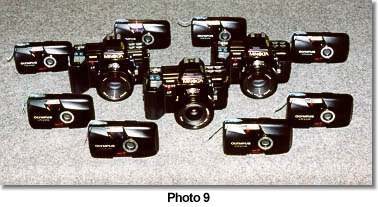
Once the desired photographs have been defined, what is the best choice for the camera payload? I have written articles (HPR November 1997) about the best choice of cameras that should be used for rocket photography. By far the most important feature of a camera needed to get great shots is the shutter speed. The cameras (Photo 9) were chosen for their fastest shutter speed and their adaptability for rocket flight. All electrical connections, battery and film doors, and the lens (SLR's) are taped to prevent inadvertent "mishaps" preventing the cameras from taking pictures when they are supposed to.
Cameras 1 through 8
The eight point and shoot cameras are the Olympus® Stylus Epic. It is an ultra compact camera with a top shutter speed of 1/1000th second and a very fast 35-mm f2.8 lens. Its film advance rate is slow, only one picture every 3 seconds, but that is not a problem for its purpose. The cameras take a picture every 5 seconds and the descent rate is about 15 feet per second. That means a picture is taken every 75 feet in altitude during descent on the parachute. Since the horizontal field of view of the cameras is 54.4°, there is a 9.4° overlap of the pictures. The film is Kodak® Royal Gold 100 ASA that has the DX coding changed to 400 ASA. Pushing the film ensures the camera has its automatic settings set to the fastest shutter speed but still does not degrade the quality of the photographs.
Cameras 9 through 11
The choice for the three SLR cameras (cameras 9-11) is the Minolta® Maxxum 7000 camera. It has a 1/2000th second maximum shutter speed, which is necessary to freeze the rapidly changing image. The aperture is set depending on lighting conditions at the time of launch. Also, this camera has an external connection to trip the shutter, which makes connecting the camera to the timing circuit easy. Although it is an automatic camera with auto focus, it is set to manual exposure and manual focus for reliability. Focus will be set to infinity. These cameras are set to shoot in continuous mode at 2 frames per second. The only time that these cameras actually shoot in continuous mode is at booster separation. For all other photographs the relays that controls these cameras are not closed long enough for more than one picture to be taken.
The two cameras looking down the side of the rocket, cameras 9 and 10, have a 50-mm f1.7 lenses and use Kodak® Royal Gold 100 ASA film. The camera at the bottom of the payload section, camera 11, has a 28-mm f2.8 lens and uses Kodak® Royal Gold 25 ASA film. The lenses and choice of film were selected for their angle-of-view and depth of field characteristics. Slow film speed is used for the smaller grain size, for better quality photographs.
Ejection Circuits
Although not a true payload, the ejection circuits are used for specific features that each one has. The Adept® PST941 timer is a high current timer even though it ignites a low current electric match. Its timing resolution is 0.1 second with a maximum delay of 25.5 seconds. The timer is used as the primary ejection circuit to have an accurate delay between the booster separation and the payload separation.
An altimeter is used as a backup ejection circuit to deploy the parachutes at apogee regardless of when that occurs. The Black Sky® ALTACC recording altimeter is used since it records both barometric pressure altitude and it measures acceleration from which altitude can be calculated. Another feature of the ALTACC is that it records data for over four minutes. This may seem excessive for a flight that lasts about 20 seconds to apogee, but the data is used to accurately measure the descent rate and to determine the altitude the photographs are taken at.
 SUCCESSFUL LEVEL 3 FLIGHT!
July 30, 1999
LDRS 18
Rocket - Scratch My Mind's Eye
Weight - 110 lbs
Motor - Aerotech M1939
Altitude - ~3700 feet
The Flight
With family and friends coming in from out of state just to watch my flight I was a little pressured to fly at a particular date. Months in advance I chose to fly on Friday at LDRS to minimize their time lost from work and to allow me enough time to drive back across country. It would have been a very long drive if I wasn't bringing back lots of exposed film and a very large rocket intact.
As the launch date approached, the forecast was for increasing winds. I knew I had better launch early. I set up the pad the night before and the payload was prepped before I even arrived at LDRS. With the few finishing touches completed we started to load the rocket onto the pad. But I still had to turn on 11 cameras, activate 4 ejection circuits, and the camera timing circuit all while standing on a ladder that was too short and with winds that were too gusty.
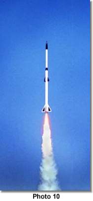
Darren Owens had the same idea about flying his Fat Boy early, but he was ready to go. We paused while he launched and he had a very nice flight but the weather cocking was severe, and the Fat Boy was marginally stable. Now it was my turn with an over-stable rocket! The launch pad paid off. It was designed to support 100% of the weight of the rocket without the rail attached. The M1939 lifted the rocket smartly with only a slight arc over the crowd (Photo 10). I couldn't have asked for a better trajectory since the winds would carry the camera payloads back over the crowds.
I started breathing again when I saw both chutes carrying my rocket safely back to Earth. Removing the cameras indicated that one of the eight point shoot cameras failed to take pictures. Since four were activated by a single relay I must have failed to completely open the cover to turn on the camera. However, I knew I would be still getting over 360 photographs.
Analyzing the altimeter data and photographs did indicate a few glitches. Instead of the booster separating a few seconds early while it is still nearly vertical, it was right at apogee with the rocket horizontal to the ground. Also the mirrors were not tested prior to flight and it turned out that they were not at the desired angle. Instead of having overlapping pictures, there is a gap between them! Along with one of the cameras not working, I did not get exactly the photographs that I wanted. But I was not too disappointed. Several shots came out very nice. I received my level 3 certification, and got back all the cameras and the rocket.
Overall it was a good day.
Sponsored Ads


 |
 |