| Manufacturer: | Estes  |
If you are interested in filming digital video from the
perspective of an estes rocket itself, then you've come to the right place.
What follows is a project which was inspired by the
Eye
Soar design. Mine is simpler and uses only the parts from two Estes
Stormcaster rocket kits, an Aiptek 1.3 Pencam and a bit of padding material.
Below are the simple steps required to build a D12 powered rocket with on board video.
 1. First you must purchase two Stormcaster kits and an Aiptek
Digital Pen Camera. Believe it or not these incredible little cameras are
sometimes on sale for as little as 20 dollars. When they originally came out
they were nearly 100 dollars. I purchased mine on sale for 39.99 down from
59.99 Go to www.aiptek.com to learn how to
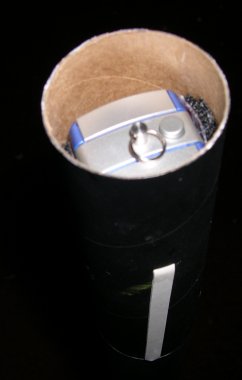
purchase yours. Mine is the Mini Pen Cam 1.3 although it also says Mega Cam on
it. The newer SD Pen Cam is a bit larger and may not fit very well in the
Stormcaster body tube. These cameras support up to 640 by 480 video and have
very impressive image quality because they use a good lens. They also support
two different video modes. Here is a picture of the camera I use.
1. First you must purchase two Stormcaster kits and an Aiptek
Digital Pen Camera. Believe it or not these incredible little cameras are
sometimes on sale for as little as 20 dollars. When they originally came out
they were nearly 100 dollars. I purchased mine on sale for 39.99 down from
59.99 Go to www.aiptek.com to learn how to
purchase yours. Mine is the Mini Pen Cam 1.3 although it also says Mega Cam on
it. The newer SD Pen Cam is a bit larger and may not fit very well in the
Stormcaster body tube. These cameras support up to 640 by 480 video and have
very impressive image quality because they use a good lens. They also support
two different video modes. Here is a picture of the camera I use.
2. Build the lower half of one of the Stormcasters as usual including the insertion of the coupler at the end of the lower body tube. NOTE: Although it is not necessary at this point, you may want to slide the bottom section's coupler in an additional amount equal to the thickness of the engine mounting rings. This will probably be approximately 1/16th of an inch. If you do not slide it in this much further then later you will need to trim the top end a bit to make a clean fit with the payload bay bottom.
3. Now you will want to take one of the upper body tubes from either of your kits and cut off the top 5.5 inches of tubing. This will become your payload bay for the camera. The bottom piece that you have left after cutting off the payload section now needs to be glued to the coupler on the lower section of the rocket.
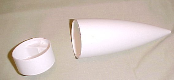
4. Now take one of the nose cones and cut off the complete section that would normally slide into the top of the rocket. This will become your payload cup. I used a razor saw which is available at any hobby shop or Michaels Arts and Crafts stores etc.
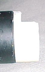
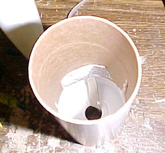 5. Now take one of the shock cords and
using the tri fold method, position and glue the mount up into the 5.5 inch
payload tube about the thickness of the lower nose cone section plus half of
one of the couplers. You can figure this out by taking the bottom nose cone
piece and inserting it cut end first into one end of the 5.5 inch body tube.
You then slide half of one body tube coupler into the body tube behind the nose
cone piece(Or use the lower rocket section with it's already glue coupler).
Push the the coupler in until it is halfway. Take the coupler out and note
approximately how far in the piece of nose cone has been pushed. For good
measure you will want to place the tri fold mount a little forward of where you
estimated, just so you have enough room later. The image below [right] is
looking in from the top of the 5.5 inch section down to the nose cone section
forming the cup with the tri fold mount just above it.
5. Now take one of the shock cords and
using the tri fold method, position and glue the mount up into the 5.5 inch
payload tube about the thickness of the lower nose cone section plus half of
one of the couplers. You can figure this out by taking the bottom nose cone
piece and inserting it cut end first into one end of the 5.5 inch body tube.
You then slide half of one body tube coupler into the body tube behind the nose
cone piece(Or use the lower rocket section with it's already glue coupler).
Push the the coupler in until it is halfway. Take the coupler out and note
approximately how far in the piece of nose cone has been pushed. For good
measure you will want to place the tri fold mount a little forward of where you
estimated, just so you have enough room later. The image below [right] is
looking in from the top of the 5.5 inch section down to the nose cone section
forming the cup with the tri fold mount just above it.
6. You will want to run the shock cord out through the hole in the bottom of the cup and place a thick ring of white tacky glue or other glue you are comfortable with using inside the bottom of the 5.5 inch body tube. You want the glue ring to start at least half the coupler's length inside the tube. This is so there is no dried glue later which will obstruct the coupler of the bottom rocket section. Once you have your ring of glue inserted you want to insert the bottom nose cone cup section again with the cupped part facing up as seen in the above photo. Once the cup is slid in you will QUICKLY take either a coupler piece or the bottom rocket section and slide the coupler into the bottom of the 5.5 inch payload section, pushing the plastic piece to it's final resting spot. At this point the cup and the tri fold mount may be allowed to dry. DO NOT leave the coupler in the bottom of the 5.5 inch tube!
 7. You now need to create your
sealing assembly to prevent hot gases from entering the payload bay. This is
done using the notched engine mount ring from your second Stormcaster kit along
with it's punched out middle piece. First punch out the center piece that you
would normally discard. Do not discard this piece! You now need to enlarge the
notch which would normally accommodate the engine retaining clip so that it is
just wide enough to allow the shock cord to pass through. You then want to put
some white glue around the inside of this engine mounting ring. Now take the
punch out piece and reinsert it back into the ring. It should fit perfectly and
you will see your flat notch at the bottom where the shock cord will eventually
come out. You will want to make sure the fit between the punch and the ring is
nice and flat to make a good seal. Now using your finger smear more white glue
around the edge of where the punch out piece meets the inside edge of the
engine mount ring. Do this on both sides. You now want to prop this piece onto
something so that it does not dry deformed or get stuck. You can rest it on
part of the plastic from your kit bag, or on wax paper. I laid mine across the
middle of a roll of tape. If you leave the engine mounting ring in it's parent
piece of press board you have more material to prop it with as is seen in my
picture below. Notice the perfect seal between the inside edges of the punch
out piece and the ring. Also notice the notch now perfectly sized to fit the
shock cord.
7. You now need to create your
sealing assembly to prevent hot gases from entering the payload bay. This is
done using the notched engine mount ring from your second Stormcaster kit along
with it's punched out middle piece. First punch out the center piece that you
would normally discard. Do not discard this piece! You now need to enlarge the
notch which would normally accommodate the engine retaining clip so that it is
just wide enough to allow the shock cord to pass through. You then want to put
some white glue around the inside of this engine mounting ring. Now take the
punch out piece and reinsert it back into the ring. It should fit perfectly and
you will see your flat notch at the bottom where the shock cord will eventually
come out. You will want to make sure the fit between the punch and the ring is
nice and flat to make a good seal. Now using your finger smear more white glue
around the edge of where the punch out piece meets the inside edge of the
engine mount ring. Do this on both sides. You now want to prop this piece onto
something so that it does not dry deformed or get stuck. You can rest it on
part of the plastic from your kit bag, or on wax paper. I laid mine across the
middle of a roll of tape. If you leave the engine mounting ring in it's parent
piece of press board you have more material to prop it with as is seen in my
picture below. Notice the perfect seal between the inside edges of the punch
out piece and the ring. Also notice the notch now perfectly sized to fit the
shock cord.
8. Once the above assembly is dry you need to gently push this piece out of it's parent piece of press board. I recommend using an exacto knife to remove the little bindings holding it in so that you do not damage your assembly or warp it. Now thread the loose end of the shock cord through the notch. Make sure it is not twisted and that it is flat in the notch. At this point you can either insert a ring of glue just below the plastic cup or not. I recommend simply inserting the assembly and then dropping the loose end of the shock cord into the bottom rocket section so that you can push this piece into place using the coupler which is glued to the bottom section. It should push it flat against the bottom of the payload bay plastic cup. Now add a glue fillet around the inside of the body tube where it meets your new 'firewall' assembly. Once this is dry you may notice that when the bottom section is fitted with the payload bay that it has about 1/16th inch of space between the two sections. Above I mentioned pushing the coupler in this amount so as to accommodate the firewall assembly. If you did not push it in this extra amount then simply cut off a ring of material around the end of your bottom section's coupler so that when you slide the two together, they fit snugly.
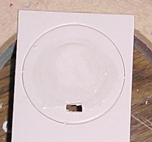
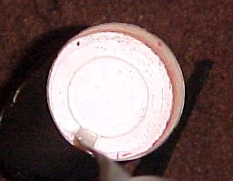
9. You should have a perfect seal now at the base of your payload area. If you want to you can add glue around and in the notch where the shock cord goes in if the seal is not complete. This prevents hot gases from entering your payload bay. The image below should resemble what you have done.
 10. Now you need to take your
unused nose cone from one of your kits and using your razor saw, cut the angled
section off of it's base. It will then look like the image below. Notice the
bit of plastic which normally creates the eye for the loop of parachute cord
has also been removed. NOTE: In this example my nose cone is already
painted black in this case because I am using parts from a prior Stormcaster to
some degree.
10. Now you need to take your
unused nose cone from one of your kits and using your razor saw, cut the angled
section off of it's base. It will then look like the image below. Notice the
bit of plastic which normally creates the eye for the loop of parachute cord
has also been removed. NOTE: In this example my nose cone is already
painted black in this case because I am using parts from a prior Stormcaster to
some degree.
11. Once you have gotten to this point you will want to slide in your camera and see how well it fits. You should be able to slide the nose cone in on top of it. If you cannot then you will need to cut a notch out of one side of the nose cone base. This is pictured below. The notched area will fit over the front of the camera and lens. Note that you also may want to add a layer of masking tape to the base of the nose cone to provide a snug fit.
 12. Now you must decide how you want to
secure the camera. First I recommend taking a complete strip of estes wadding
as it would come in the bundle from a wadding pack and insert this crumpled up
into the plastic cup. This provides some cushioning and is non flammable just
in the off chance some how a flame got through. You can use various fluffy
filler material but the estes wadding will not burn in that 1 in a million
chance that you might get a spark through. With the camera sitting on either
the wadding ball or other fluff, you then need to take note how your camera
fits in the tube and measure where the lens sits in relation to the outside of
the payload tube. You will want to remove the camera and then using a very
sharp exacto knife cut a square or round hole for the lens to see through. Once
you have done this you will want to use felt pads or other material to brace
the camera correctly so that it does not move. In my example I use squares of
Velcro sandwiched together. This is shown below. I also have a U Shaped piece
of paper inserted to keep the sticky glue from the Velcro pieces off of the
camera. You may want to consider adding filler material inside the nose cone as
well in case the camera comes loose. However, I think this is less of concern
than the nose one coming off entirely. You may want to secure it in someway.
The lens hole is to the right in the picture below.
12. Now you must decide how you want to
secure the camera. First I recommend taking a complete strip of estes wadding
as it would come in the bundle from a wadding pack and insert this crumpled up
into the plastic cup. This provides some cushioning and is non flammable just
in the off chance some how a flame got through. You can use various fluffy
filler material but the estes wadding will not burn in that 1 in a million
chance that you might get a spark through. With the camera sitting on either
the wadding ball or other fluff, you then need to take note how your camera
fits in the tube and measure where the lens sits in relation to the outside of
the payload tube. You will want to remove the camera and then using a very
sharp exacto knife cut a square or round hole for the lens to see through. Once
you have done this you will want to use felt pads or other material to brace
the camera correctly so that it does not move. In my example I use squares of
Velcro sandwiched together. This is shown below. I also have a U Shaped piece
of paper inserted to keep the sticky glue from the Velcro pieces off of the
camera. You may want to consider adding filler material inside the nose cone as
well in case the camera comes loose. However, I think this is less of concern
than the nose one coming off entirely. You may want to secure it in someway.
The lens hole is to the right in the picture below.
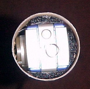 13. Here you see the camera
mounted inside the payload bay.
13. Here you see the camera
mounted inside the payload bay.
14. And now is a shot of the lens looking out from it's nest inside the payload
section. 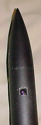
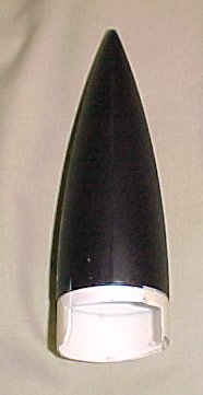
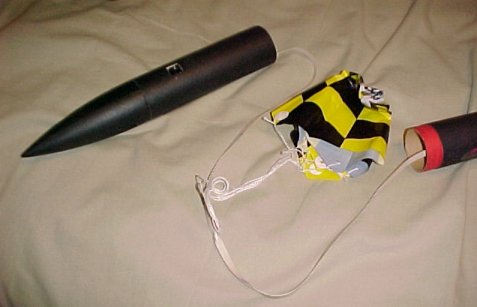
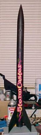
15. The last step is to attach a parachute in the middle of the shock cord
between the payload bay and the lower rocket section. Use whatever you feel
comfortable with. A larger chute will provide a softer landing but may carry
the rocket farther away, increasing the chance of losing it. I don't recommend
using a swivel since they seem to fail. You may want to tie a second chute at
the base of the payload bay. You may also want to then move the middle chute to
the top of the bottom rocket section. A nylon chute may be best to prevent heat
damage. Below are two images of the complete rocket.
Firing Your Rocket
My method is simple. First set the camera's video mode to either high or
low resolution. Then insert it into the rocket and make sure the lens is
positioned correctly. Make sure the focal length is set on infinity(Not the
flower setting). You might want to use a piece of scotch tape to secure the
lens setting in place. Now push the shutter button and quickly attach the nose
cone. Get back a safe distance and press your launch button. There are several
ways to make a quick launch and you may want to experiment to see what works
best for you. The camera I use provides me with about 30 seconds of high
resolution video which is plenty of time to get the nose cone on and fire the
rocket. The lower resolution setting will give you much more time and you can
take a slightly more leisured pace back to your launch controller. Once you
retrieve your rocket you can download the video to a laptop or your home
computer in the normal manner.
Due to the occasional hard landing and the fact that I wanted the camera to descend at least somewhat vertically, I have created the following modification for this setup. You first need to cut a small 1/4 inch slot in the back of the payload bay about 2 inches from the top. It should line up approximately with the lens view port cutout on the other side of the payload tube. This slot is indicated below.
You now need to feed the shock cord from your second Stormcaster kit through the slot and into the body tube. Make sure it goes in flat and not twisted.
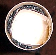
Now you want to create a tri fold paper glue mount using this end of the shock cord. You should place this mount towards the bottom of the payload bay inside. A closeup of this is shown below. The cord should come in taut and flat and directly into it's mount. You do NOT want any slack in this joint. The mount of the lower shock cord is also visible in this image.
 You should now
cut a notch in the coupler tub which mates with the payload bay. This will
allow this new shock cord to be passed into the lower body tube where it is
tied to the parachute. I recommend using a swivel for the shock cord to
parachute attachment so that the camera assembly does not spin on the way down.
However, you want to use a strong swivel sense it will be carrying the weight
of the entire rocket assembly. It does not need to be as strong as you would
think though because the shock of ejection is still absorbed by the lower shock
cord. The swivel only connects to the parachute, supporting the rocket's weight
on the way down.
You should now
cut a notch in the coupler tub which mates with the payload bay. This will
allow this new shock cord to be passed into the lower body tube where it is
tied to the parachute. I recommend using a swivel for the shock cord to
parachute attachment so that the camera assembly does not spin on the way down.
However, you want to use a strong swivel sense it will be carrying the weight
of the entire rocket assembly. It does not need to be as strong as you would
think though because the shock of ejection is still absorbed by the lower shock
cord. The swivel only connects to the parachute, supporting the rocket's weight
on the way down.
This next image below shows the new shock cord tightly laying against the payload bay and passing through it's notch in the lower section. That's it! Now you're ready to launch!
These are frame captures from some of my recorded video.
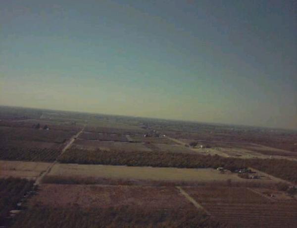
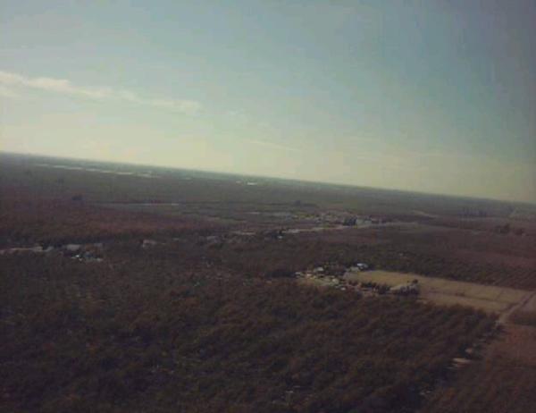
These clips are compressed for bandwidth purposes and do not represent the
full capabilities of the camera. They are a good representation however.
Video 1 Video 2
Sponsored Ads


 |
 |