Qualified Competition Rockets Ultimate II (helicopter)
Qualified Competition Rockets - Ultimate II (helicopter)
Contributed by Jose Andrade-Cora
| Construction Rating: | starstarstarstarstar_border |
| Flight Rating: | starstarstarstarstar_border |
| Overall Rating: | starstarstarstarstar_border |
| Manufacturer: | Qualified Competition Rockets  |
Brief:
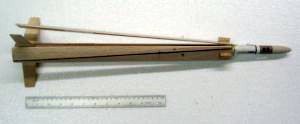
This is a single-stage model rocket for 18mm engines. Recovery is by
helicopter, of the spinning hub variety. This means that the rocket airframe is
intended to stay still, while the rotors spin. As with most QCR models, it is
designed for competitive use.
Construction:
The kit comes packaged in a heavy gauge plastic bag with a blue QCR header
strip labeled with the model number, #100. In the bag you will find a BT-20
size body tube, balsa nose cone, balsa stock for the helicopter rotors, fins,
and hinge stops. Also included are plastic rotor hinges, rubber bands, metal
hooks, elastic thread, and 3 paper rings. All parts were accounted for and in
good shape, except for the 3 rings, which were slightly out of round. This may
have occurred because the kit was in storage for a couple of years before I got
around to building it. The problem was easily solved by slipping the rings over
the body tube and keeping them there for a few weeks. The balsa stock for the
rotors and fins was SIG contest-grade balsa. However, the nose cone and the
rings had a few rough edges. Nothing serious. For a $13.00 rocket (as of
3/14/05) you can't beat the value.
The kit includes a 6 page instruction booklet...if you want to call it that. The "instructions" are so disorganized, that I opted to rewrite them before attempting to build the kit. The only positive comment that I can make of the original instructions is that they are well illustrated. I don't mean that the illustrations are Estes quality but what is meant that the illustrations effectively do the job of showing the modeler what to do in specific instances.
The kit is meant for experienced modelers. In their website, the manufacturer has the kit a a level of difficulty of 4. I will agree with that rating. This is because of the amount of careful balsa cutting and shaping needed and the delicate use of different glue types in attaching the hinges, rotors, etc. The disorganized instruction booklet does not help either!
The build begins by cutting the rotors and fins from the balsa stock. No laser cut parts here! All cutting is done the old fashioned way with templates, hobby knife, and a straight edge. The rotors need to be airfoiled then cut. The end result is that you get a "bent" rotor, when looking at a cross-sectional view. Airfoiling and cutting the rotors is probably the most labor intensive step in the building process, as each rotor is 18" long. Once the rotor has been airfoiled, it feels somewhat fragile especially given the length.
The instructions don't call for airfoiling the fins, so I chose to round the leading edge and sand the trailing edge to a knife edge. Given the relatively large frontal area of the body tube/rotor combination, the airfoiling of the fins (or lack thereof) would probably be immaterial. Also, given the large radial length of the fins, I didn't want to weaken them by too much sanding.
The next step is to attach the hinges to the spin hub. This is the most delicate of the steps glue wise. You must use the right type and amount of glue here or you'll end up with a set of useless hinges. Go ahead, ask me. That is exactly what I did. Although I used thick CA to tack the hinges to the spin hub, I used too much in one of them, gluing the hinge shut. Luckily I had an extra hinge in my spares box, which Ken Brown had thrown in as a freebie in a previous order. All's well that ends well! Ideally, this problem could be prevented by changing the instructions so that the hinges are tacked on while holding the hinge end of the spin hub upwards rather than downwards. The problem lies in how to align the hinges while doing this. The step is finished by winding sewing thread around the hinges to secure them to the spin hub. Holding the hinge side of the spin hub upward, affix the thread with thin CA. Since the kit did not provide sewing thread, I used size 69# Kevlar® thread.
There is yet another pitfall here. This is a spin hub helicopter rocket. In other words, the hub is supposed to spin about the longitudinal axis of the rocket, over the body tube. If the spin hub is in any way out of round, it will not work correctly causing it to rub and bind against the body tube. It is possible to start with a perfectly round spin hub, glue the hinges, and wrap the sewing thread according to instructions but still distort the shape of the spin hub. (I did this too!). My way around this problem was to wrap a few turns of masking tape about an expended engine casing and insert it in the spin hub before securing the hinges with the sewing thread. The casing will serve to keep the shape of the spin hub while you wrap the sewing thread.
The next step is to attach the rubber band hooks to the spin hub and the rotors. No surprises here, just sand and lubricate the body tube where the spin hub will be located. You may get away by just sanding the inside of the spin hub and leaving the body tube alone. The glassine covering of the body tube is very smooth, however, I followed the instructions and sanded both the spin hub and the body tube. The step is finished by gluing the lower support ring for the spin hub and the fins to the body tube. The fins are so long compared to the width of the root edge that there is a fair amount of flex even after the glue dries and fillets are applied.
The last big step deals with gluing the rotors to the hinges. To do this appropriately (and easily), you need to extend the lines in the fin alignment drawing to about 20". I will not go into how to do this in this review, but suffice to say that a few sheets of poster board from your local school supply store will come in handy. You then place the spin hub back on the engine casing, align the rotors with the 120° lines, and tack the rotors to the hinges with a small amount of thin CA. If anything appears out of place, adjust the rotors and tack again. When you are satisfied with the positioning of the rotors, glue with epoxy. Epoxy is dense, so use the smallest amount that will do the job. Finish the rotors by affixing the balsa "stops" so that the rotors have a 6" dihedral when fully open. By the way, my original instruction booklet illustrated a 2" dihedral. It also had 12" rotors, as opposed to 18". I emailed Ken on this point and he promptly mailed me updated instructions that had a 6" dihedral and the right rotor length. Bad instructions! Good service!.
The remaining construction steps are simple and should be uneventful. See the rewritten instructions for them.
Finishing:
This is a QCR bird, so it's primarily designed for competition, therefore it is
OK to fly it "naked"--that is unfinished. Looks are not a priority
here. For those guys out there that must finish their rockets to find inner
peace, a thin coat of clear enamel may be what the doctor ordered, as it will
keep the rotors from absorbing moisture, just be ready to pay for the weight
cost. An alternative would be to "paint" the rotors with thin CA and
sand the blades smooth afterwards. This would strengthen the rotors and take
care of the moisture problem as well.
Construction Rating: 4 out of 5
Flight:
The flight characteristics of the Ultimate II are excellent. Long flight times
with stable trajectories were the norm. While the original instructions had the
Estes C6-3, Apogee D3-3, and Apogee C4-3 as recommended engines, the second set
of instructions that Ken sent me only recommended the Estes engine. In order to
test stability and other flight characteristics, I flew the bird with Estes
A8-3, B6-4, and C6-3 engines. The flights were all acceptable, although the
A8-3 seemed wobbly (read: underpowered) at first. Both the B6-4 and C6-3
flights were arrow straight and ejected at or near apogee. A good engine to
test would have been the C6-5, as I think the 3 second delay was too short on
the C engine, while the 4 second delay was perfect on the B engine.
The rocket requires no wadding for flight preparation and the engines were retained using masking tape. Engine retention is necessary for NAR contest flights. The preflight preparation would be a breeze except for the need to pass sewing thread through the body tube and then knot so that it holds the rotors in place on the way up. This is hard to do in the field without an assistant.
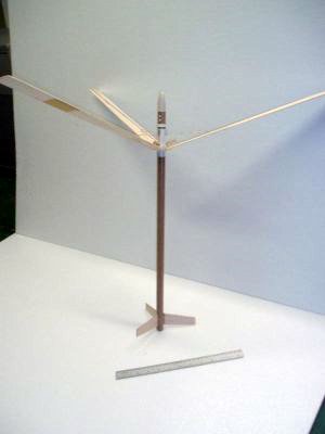
Recovery:
One curious aspect of the recovery was that, in all cases, the whole rocket
spun in the air on the way down instead of having the spin hub rotate about the
body tube. Probably there was still too much friction between the spin hub and
the body tube. However, I doubt whether any amount of sanding and lubrication,
limited by the need to have a viable body tube and spin hub, would reduce
friction to the point of making it smaller than the drag of the body tube
rotating in the air.
As far as wear and tear goes, after three flights, the only apparent damage was that the exhaust gases were beginning to melt the Mylar plastic that protects the rotors. Probably could do better by gluing a small piece of aluminum foil to the back of the rotors rather than the Mylar tape. On the other hand, durability may not be a primary design objective on a competition bird.
Flight Rating: 4 out of 5
Summary:
This is a very nice rocket. Good materials and great flight characteristics.
Construction, however, is a bit challenging. Perhaps the extra difficulty of
the spin hub type helicopter is not worth the effort. QCR manufactures other
helicopter models of similar size without the spin hub design (like the High
Rotor I). I recommend the Ultimate II to any experienced builder looking for an
unusual rocket or someone aiming to fly competitively.
PROs: Good materials, light and strong rocket, good flight characteristics, customer service, and price.
CONs: Poor instructions, difficult construction, and spin hub didn't work.
Overall Rating: 4 out of 5
Other:
QCR #100 -- Ultimate II Instructions (Rewritten and Annotated)
- Cut out and shape rotors.
- Cut out rotors from balsa stock.
- Tip: Replicate markings of sample rotor on the other two. Place a mark on the tip of each rotor at the middle of the blade.
- Airfoil outer 12" of each rotor.
- Cut rotor blades along diagonal shown in sample. You have a choice between a "standard cut" (almost along the rotor's main diagonal) or a shorter "optional cut" Don't cut all the way through. Instead, cut halfway and then bend along the cut line. Spread glue inside cut (medium CA). Use round toothpicks under the break while the glue dries. Tip: Using masking tape along the sides of the blade, tape the rotor to your worktable over the toothpicks. This keeps the cut open while the glue dries. Rubbing the toothpicks with petroleum jelly will keep them from sticking to the rotor permanently, in case the CA glue wicks over to the underside of the blade.
- Cut out and shape fins.
- Cut out fin pattern from instruction sheet. Tip: Replicate it on a piece of cardstock. Discard the paper fin pattern.
- Trace fin pattern on balsa stock. Tip: Make sure the leading edge is parallel to the wood grain.
- Cut out the fins.
- Sand the fins as appropriate. Tip: Airfoil for competition use.
- Sand nose cone as needed.
- Punch 2 holes on BT. (4 holes were already punched in my kit.)
- Glue hinges onto outer spin hub.
- Glue 18mm engine casing in center of fin alignment drawing. Let dry. Tip: Wrap a few turns of masking tape around engine casing to make a better fit for spin hub.
- Place spin hub on casing. Draw lines on spin hub 120° lines apart, parallel to its longitudinal axis (Note: Already done in my kit). Align with lines on the drawing.
- Draw lines through center of hinges.
- Fold hinges at right angles. Align hinges with lines on the drawing and lines on hub. Put masking tape under hinges to keep them from sticking to the drawing.
- Tack hinges to hub. Tip: Use thick CA (sparingly). Don't let glue get to the hinge pins. Smear the joints with petroleum jelly to protect it from the glue.
- Secure hinges to spin hub by winding the sewing thread around the hinges. Glue thread in place. CRITICAL: Don't get glue on hinge pins. Tip: Keep the glue away from the hinge joint by holding the hinged end of the spin hub upward during this step.
- Attach metal hooks to spin hub by aligning them with 120° lines on forward end of spin hub. Glue them on the outside of the hub. Tip: This is a high stress joint. Use 5-minute epoxy.
- Glue metal hooks (for rubber bands) to rotors by locating position of hook along each rotor's longitudinal axis, 4" from the hinge edge.
- Work on body tube.
- Draw a line around the body tube 3 5/16" from the forward edge of the tube. Slide and glue the lower ring to body tube. The forward edge of the ring should lie on the line drawn around the body tube. Tip: CA grabs too fast for applications in which pieces have to slide into place. Use carpenter's (yellow) glue.
- Sand and lubricate the inside of the spin hub and the outside of the body tube. Use pencil tip for lubrication.
- Glue fins to body tube. The aft edge of the fins should be 3/8" from aft edge of body tube. Use medium CA or carpenter's (yellow) glue. Tip: Lightly sand area where fins are to be glued.
- Protect the nose cone from being burned by the ejection gases by covering the shoulder end (not the sides!) with a coat of epoxy. Do the same for the front end of the body tube (near the punched-out holes).
- Glue rotors to hinges.
- Place hinged spin hub on engine casing previously glued to the fin alignment drawing. Align hinges with 120° lines. Use masking tape under hinges. Tip: Make the drawing bigger by gluing the original drawing to poster board backing. Then extend the alignment lines to 20" from the center of the drawing.
- Align rotors with 120° lines. Each line should be in the middle of the hinge and the middle of the rotor. Tack rotors one at a time with CA.
- Put spin hub on body tube and check rotor alignment. Rotors should lie straight between the fins. Open rotors should also be equidistant from each other (about 31" between tips). If needed, adjust and tack again.
- After all adjustments are made, glue rotors and let dry. Tip: This is a high stress joint, use epoxy.
- Cut hinge stops out. Locate position of stop along a rotor's longitudinal axis that will allow the rotor to open to a 6" dihedral, measured at the rotor tip. Glue and let dry. Repeat for other 2 rotors. Tip: Tack rotor stops in place first with thin CA, then glue with epoxy. For a 18" rotor, the specified dihedral is equivalent to an angle of 19.5°
- Draw a mark on the body tube, 5" from the aft end, aligned with one of the fin placement lines. Punch or drill a 1/16" diameter hole clear across the body tube. You may use a large needle for this.
- Protect the rotors by covering them with Mylar tape, at the point where they would meet the holes made in Step 11.
- Place spin hub on body tube. Slide upper ring onto the body tube and glue with carpenter's glue. Allow a small gap (say 1/16") between spin hub and top ring. Tip: Apply a light coat of petroleum jelly on the gap to protect it from the glue. CA grabs too fast for applications in which pieces have to slide into place. Use carpenter's (yellow) glue. Make sure to wipe off all excess glue.
- Glue the nosecone in place.
 |
 |
Flights
|
|