Roachwerks Custom Turnings Soyuz TM
Roachwerks Custom Turnings - Soyuz TM
Contributed by Chan Stevens
| Construction Rating: | starstarstarstarstar_border |
| Flight Rating: | starstarstarstarstar_border |
| Overall Rating: | starstarstarstarstar_border |
| Manufacturer: | Roachwerks Custom Turnings  |
Brief:
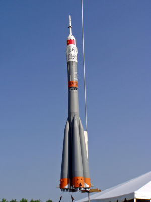
1/64 scale model of the workhorse of the Soviet space program, single stage kit that can be built to fly on either a
single 24mm motor or with an additional four 18mm motors.
The kit was offered as a limited edition run several years ago and has long since sold out, although if you ask Sandman (his handle on various online forums) nicely, you might be able to talk him into making another batch.
This review is based mainly on my first-place NARAM-50 scale entry, which was a significantly modified version of the kit, and included a 24mm motor plus 16 Micromaxx motors in the boosters, fired using a customized spider ignition system. I will try to indicate customizations that are not part of the kit, but the photos might reflect my model, not necessarily what comes out of the box.
A photo album of more detailed pictures, many in high resolution, can be viewed online.
Note that all references to stages in this review are to the actual Soyuz vehicle, not the model rocket kit. The kit is strictly single stage.
Construction:
The kit came packaged neatly in a surprisingly small box, but none of the fragile parts were even slightly damaged.
In part, this was because they were packed using small pouches of dog barf as padding. Very cool, having a rocket kit
come with its own recovery insulation.
The kit does not include a parts list, but from memory and scanning over the model, I think the main components included:
- Hardwood dowel tower (custom machined)
- Balsa 3rd stage upper module (custom machined)
- BT-60 upper stage body tube
- Balsa 3rd stage lower transition (custom machined) **
- Balsa 2nd stage nose cone/cap **
- BT-55 second stage main body tube
- 4 BT-60 booster body tubes (lower section)
- 4 Balsa booster nose cones
- 24mm motor mount assembly (metal hook, rings, tc.)
- 4 18mm motor mount assemblies (no hooks)
- Basswood fin stock
- Laser-cut fiberboard details (interstage truss wrap, 3rd stage screens)
- Cardstock shrouds (2nd stage transitions, strap-on bodies, engine bells)
- Lots of resin-cast details
- Balsa/Plastruct stock for smaller details
- Silver Monokote adhesive trim
- Waterslide decals
- Estes 18" plastic chute
** - supplied as a single piece, joined by a dowel
This is certainly not a quick or easy build, and I would rate it every bit of a 5 on the 1-5 scale for difficulty. The instructions are fairly well written and definitely from the perspective of an experienced modeler, but there are several areas where you're given general guidelines or suggestions and left to figure it out on your own. If you need help though, Sandman is just an email away and is absolutely amazing in his willingness to bend over backwards to help. Throughout my construction project, we probably swapped more than 50 notes, and there were numerous instances where he would scramble and make either a replacement or a slightly customized part for me (sometimes free, sometimes for a reasonable fee).
OK, at the start of construction, you decide whether or not to load the 4 strap-on boosters with functional 18mm motor tubes. If going for a single-motor configuration, you can skip a few construction steps but will miss out on the fun of the cluster. In my case, I skipped the 18mm motor tubes in favor of a highly customized series of 6mm clusters, 4 per strap-on.
To build the lower sections of the strap-ons, you start with a short piece of BT-60 tube, a pair of centering rings, and the optional 18mm motor mount. If using the mount, the centering rings need to be carefully marked with alignment ticks, as the center hole for the motor tube is off center quite a bit, and it's important to try to angle these through the rocket's CG in case you don't light them all (avoids asymmetrical thrust). There's a sliver of a tube coupler for the top edge, to which the shroud (body) eventually is mounted. There's also a very nicely rendered cardstock cover disk for the aft end that depicts the locations of various engine bells and details later in the process. If using the 18mm cluster option, though, this has to be converted to a removable assembly as it would cover up the BT-20 tube.
The strap-on bodies are formed mostly by cardstock shrouds, which are a lot of fun to make. These are not standard/straight shrouds, instead tapering to mount to the main body tube at an angle. Compounding this challenge is the fact that the nose cones have to slip tightly into the open top (from inside/below), and are in turn mounted at an opposing angle to mate up against a sloped transition section of the main body. Yikes! For sport flying, a few gaps here and there are probably not a big deal, but for NARAM scale this was extremely challenging, especially since I chose to paint these separately before mounting, and therefore could not really get a good fit check until very late in the process. My fin spans were off as much as 15mm, so I wound up having to make some funky little clamps to gradually pull the strap-ons back into position and hold them overnight while I used some thin epoxy to keep them in place.
Fins, by the way, are very tiny and cut by hand from basswood per a cardstock pattern. I went a little above and beyond, making the fin mounting platform from balsa--the fins were detachable on the real thing, and not mounted until the vehicle was at the pad.
For some additional fun, there's one other scale-like step you could choose to take. The aft end of each strap-on body is not actually round. This is because there are fairings that mount to the second stage that would butt up against the strap-on bodies. There's actually a small "step" cut across the inside edge of the BT-60 body tube to flatten it, which I then sealed off with a piece of cardstock and a little wedge of balsa (see photos). Without doing that, the strap-ons will really be sticking out too far at the aft end and the gaps would be pretty glaring, plus I'd imagine that would throw the thrust angles off a bit of any motors in the strap-ons...
The second stage (main body) is probably the easiest portion of the assembly. The aft end gets a standard BT-50 motor tube/centering rings/metal hook motor assembly. The forward end has two opposing transitions made from paper shrouds, supported by a couple fiberboard centering rings. As mentioned earlier, there are some resin-cast details for the aft end as well--4 fairings and 4 auxiliary motors.
At this point, you could glue the strap-ons to the second stage, but, as I indicated, painting could be an issue. The bottom section of the strap-ons is painted orange, the upper section gray (not white or olive green, a common mistake--see finishing details), and there's a silver Monokote wrap that accents them as well. Masking for this, plus trying to apply the Monokote after they're mounted strikes me as insanely difficult, especially since the second stage is all gray (no orange). Wait until after everything is painted to assemble the strap-ons and second stage.
 Mounting of the launch lug is one of those vague parts I had warned about--the instructions simply say
to mount a pair of lugs after the assembly, but offer no suggestions for where. On something with this many diameters
and such complex geometry, that's not exactly an easy decision. In my case, I had planned on using a fly-away pop lug,
so all I needed to do was drill a couple small holes for a couple pins from my pop lug plate.
Mounting of the launch lug is one of those vague parts I had warned about--the instructions simply say
to mount a pair of lugs after the assembly, but offer no suggestions for where. On something with this many diameters
and such complex geometry, that's not exactly an easy decision. In my case, I had planned on using a fly-away pop lug,
so all I needed to do was drill a couple small holes for a couple pins from my pop lug plate.
Moving on to the interstage truss and upper stage, I started to really deviate from the standard kit even more. The interstage truss is a grid pattern laser-cut from cardboard. As such, it would not provide much strength holding the two sections together during thrust with only 12 small connection points. [Note: All the early versions of the kit, including mine, had a truss that incorrectly only included 10 sections, not 12.] The way Sandman got around this was to leave the dowel used to turn the balsa pieces on the lathe in them so there's a strong ¼" round dowel holding the 2nd stage nose cone to the 3rd stage. This also does a great job of keeping the two sections vertically aligned. Unfortunately, there was no big honkin' pipe connecting the stages on the real vehicle, so I had to come up with something different. I decided to cut out the dowel (leaving a fair amount of filling/finishing work to hide the results), ditch the cardboard truss, and make my own from music wire. I used 0.050" wire originally (shown in the detail photos), but found despite my efforts to bend them as close to spec as possible, they did not line up perfectly with the carefully drilled mounting holes I had drilled, and attempting to bend them after I'd mounted them in one half tended to break away at the balsa instead. As a result, I scrapped the music wire and went with 0.050" brass rod instead--same scale accuracy, but much easier to work with. The finished model photos feature the brass truss, but I was too behind schedule while building it to have caught decent shots during the construction.
There's also a pretty cool embossed wrap to go around the second stage just below the interstage truss. Unfortunately for me, that wrap had flattened out almost completely after the years of storage, and Sandman's tool had pretty much worn down over the years, so the replacements he tried to make for me were no better.
The third stage construction, aside from the details, is pretty quick and easy as well. It consists of a lower section of balsa (very nicely turned), a short section of BT-60 (in my case there was a significant gaffe in the length, which has since corrected on his other kits), and a balsa nose section that is a work of art in terms of quality of the machining. A hardwood dowel tower goes into the end of the nose cone to complete the major structure. Before sealing everything up though, you'll want to add some nose weight to bring the CG into an acceptable position. I dry-fit the major components together, loaded up motors, and found that to get a stable CG I needed to add a couple ounces of epoxy and lead sinkers, filling almost half of the body tube cavity.
The rest of the construction is focused on the ton of details, most of which are provided, though some are left to the modeler to make by hand. If you refer to Peter Alway's Rockets Of The World drawing, you'll find most of the details included on his drawing are reflected in this kit but not quite all. If you have the more detailed Minakov drawings (available from NARTS in the Russian Scale Data Pack), you'll find that while this kit is dimensionally based upon those drawings, however, the level of detail doesn't get down to those prints. That's not a knock on the kit but a testimony to the amazing richness of the Minakov drawings.
Strap-on details include a couple resin vents per booster and a you-cut-it umbilical and conduit piece. On the aft end, there's some amazing detail work involved. I had previously mentioned the finely drawn paper disk that can be used as a locator. There's also a small "platform" pattern from paper that creates the proper cant for the engine bells. The engine bells themselves are paper shroud wraps. In my case, since I was going to have functional motors inside each one, I painted the inside of each with a very thin epoxy. As an added touch, I also glued a single wrap of Kevlar® thread around each one to serve as a semi-scale effort to replicate the tubing around them. The final detail on the aft end is the auxiliary motor "assembly", which consists of a cast resin base plus a pair of resin motors. The resin parts were of decent quality, not the greatest, and do require a bit of cleanup and void filling.
The second stage has much less detail work--a set of 4 cast fairings, 4 cast auxiliary motors, 4 embossed butterfly hinges where the strap-ons are attached, a resin conduit piece, and a you-cut-it balsa conduit.
The upper stage includes the most detail. For starters, there are the 4 screens towards the top of the command module. These are made from a laser-cut cardboard panel and legs. It's solid, not screened, and the screen effect is achieved by a printed paper pattern that is to be glued on after painting. Being an anal-retentive scale modeler though, I searched several stores for real screen that would be the right size and pattern. After striking out, I noticed my very old screen door looked about right, however, one evening when the wife was out, I sliced away a few inches that fit the bill nicely. My poor dog is the primary suspect in all household damage, deservedly so, but in this case he took one for his master. The things we do for our models...
There are about a dozen little resin doodads not worth getting into, as well as 4 resin escape motors that go on the tower. Sandman grouses in the instructions that technically there are also supposed to be 4 more intermediate escape motors about 0.080" diameter plus two 6-motor clusters that are 0.050" diameter, which he was not going to bother with. I did, making all out of various pieces of toothpicks.
Finishing:
Much like a Saturn, finishing the construction only offers a brief opportunity to sit back, admire your work, and let
out a big "Whew!". The finishing is no picnic, with a total of seven different painted colors involved. For
the most part, I used Krylon primer followed by various custom-mixed Testor's enamels sprayed on with a cheapo
single-action external mix Badger airbrush.
One note on the color scheme, which will probably look "wrong" to most casual fans of the Soyuz--the most popular photographs of the TM series are generally either the poorly developed shots that look like the main body is olive green, or launch pad shots that make it look white due to the frost on the fuel tanks. The actual vehicle was mostly gray, supported my a number of photos of the factory floor that show the gray in good lighting.
Strap-ons were all painted gray, then masked for the orange. Fins were painted silver and the aft end painted stainless. The nozzles were painted red/copper inside. After all paint had cured, I applied an adhesive chrome for the silver metallic effect.
Second stage was all gray, with the aft end (resin motors) painted steel.
Upper stage starts out with a white base, then is masked to paint the middle section gray. More masking, then the lowest portion gets orange paint. Underneath, the motors are a combination of silver and copper. The motors, by the way, are not covered in the standard kit--I made 2 different 4-motor sets out of paper shrouds from scale drawings.
The tower is all white, though there are brown sections on the larger escape motors, and the smaller escape motors have red nozzles.
The kit is designed to match either the TM-11 round or the TM-12 round. The TM-11 was a mission involving live video and a reporter for the Tokyo Broadcasting System. The TM-12 mission included Britain's first citizen in space, scientist Helen Sharman. Each flight included the flags of the respective participating countries, as well as corporate logos for TM-11. I decided to model the Tokyo Broadcasting System TM-11 mission, and applied the decals accordingly. The decals for the kit were provided by Excelsior Rocketry, which means they were excellent quality but very thin and extremely fragile. You do not want to try applying these without first treating with Microscale's decal solution, and the decal instructions make this very clear.
In my kit, the decals of the Sony and TBS logos turned out to be slightly oversized--not only non-scale, but so large that they would not fit in the proper area of the rocket. I didn't discover this until the day before turn-in for NARAM, so had to scramble to scan, resize, and reprint a set on my own decal paper. While mine fit better, they were not nearly as nice as Excelsior's.
Once all the decals were set, I hit everything with 3 coats of Testor's flat clear dullcoat, which not only helped nail the scale-like finish, but also wound up making the decals appear as though they were painted on, perfectly blending into the painted background.
Construction Rating: 4 out of 5
Flight:
Before starting on the flight report, I should probably include a few words about the mechanism I used to achieve the
clustered ignition. When you start stretching beyond 4-6 motors, clip-whips and/or spliced leads is not a very
effective ignition method, with the current getting spread too far/too thin/too inconsistently to reliably light them
all. A more effective method that's been used, particularly in international competition, is "flash pan"
ignition, where you essentially pour some black powder onto a pan, set the rocket on top of it, and light the powder.
While it does a good job of lighting the motors, it also tends to char the aft end of the model pretty badly as well.
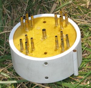
A few years ago, the Meatball Rocketry team (Josh Tschirhart in particular) introduced what's referred to as a spidered ignition system. While they didn't invent this, they published an excellent R&D report and set of plans that made this something that a modeler with average skills could pull off, and Josh also changed to Pyrodex, a much safer and more readily available powder alternative.
A spider is basically a section of large pipe (in my case, 4" PVC) with a small bowl sealed inside (mounted on top of a removable centering ring that bolts in). There are a series of small brass tubes running through the top that line up with the nozzles of the rocket motor cluster. The interior bowl is filled with Pyrodex, and when ignited (using a regular Estes igniter), the resulting flaming particles go shooting up the brass tubes (vents), eventually sneaking up into the nozzles of the black powder motors (this will not work on AP motors) to light them.
Knowing only a little about spiders and not at all sure I could pull off a 17-motor cluster (Josh's spider was for an 8-motor Saturn), much less on the small-scale MMX motors (Josh had done 18mm and 13mm motors), I turned to a member of our local club who had been using Josh's basic design for a couple years and enlisted his help. The guru, Steve Bostwick, proceeded to take my motor mount layout/design and one evening later had a basic bench test mock-up ready to test fire. We managed to light 3 of 4 motors on the test, and concluded that the 4th failed because we didn't have a standoff, which meant one motor was sitting directly on top of the vent tube, sealing it off.
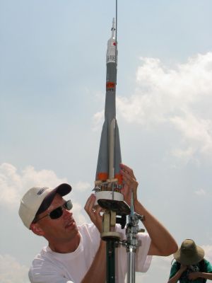
Steve proceeded to quickly knock off another full-sized version, which also included telescoping tubing so that I could individually adjust each tube to seat properly at the pad. Given the time crunch I was facing building the rocket, Steve's quick engineering/construction saved me what would have been weeks of fiddling and tweaking, and he basically flattened my learning curve.
Fast forward to NARAM...
For scale, the total score is composed of two parts--static, which is about 3/4 of the total and represents how well the model was built (finish, accuracy, etc.) and flight, which is about 1/4 of the score, and in part based on the complexity of the flight (staging, clustering, etc. get extra points). No matter how well you do in static, you can't place in the event without a safe/stable flight.
When we reviewed the static scores, I was tied for 4th behind some stunning models. However, with the potential to max out my flight score with 17 clustered motors, I felt pretty good about my overall chances as no one else had quite as high a potential flight score. I wanted to first "lock" in my score with a qualified single-motor flight though in case something went wrong with the cluster and the model was too badly damaged to fly again. As an aside, my motto for the week, which certainly applied to this event, was "what could possibly go wrong? [insert big grin here]".
I loaded up an Aerotech D15-4 (reload), wanting a little more thrust spike and total impulse than the Estes D12, but also wanting to make sure I got it back quickly and safely. Liftoff was actually a bit slow, probably due to my added nose weight, and the rocket weathercocked a little bit but generally few fine. The -4, shortest delay available for the motor, was a bit too long and it deployed just after it had turned over. I had gone with 2-piece recovery and ditched the cheesy plastic chute for a pair of 18" nylon chutes. Other than breaking off one small resin detail from the upper stage, the rocket was unblemished.
As the rest of the day played out, a few of the competitors who were behind me in static had passed over me by flying more complex flights, so I had to go for the cluster for my second (and last) flight. I had spent the better part of 2 hours casually prepping the 16 MMX motors (and went with an E9-4 central) and loading up the spider. By the time I hauled everything out to the pad, I had drawn a pretty decent crowd, no doubt in part because I had boasted that having not had any mishaps so far in the week, this would be my "Best Midwest Qualified Flight Award--Record Trial" (I'm a two-time winner, and no one has ever won 3 of this award given every year to the most spectacular flight failure at NARAM). The sun was baking down on me as I fidgeted with the tubes, sliding the rocket on, off, on again, off again, etc. working on the alignment. I had somehow managed to misplace my needle nose pliers, and rather than make another trip back to the car 200 yards away, I pressed on with as well as I could do using fingers. After about 15 minutes, I was cooked and decided that with the way the points system worked, anything more than 11 motors lighting would achieve a max, so I left a 4-motor cluster set with a nearly 3/8" gap, far too wide for the spider to reach.
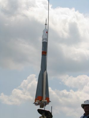
I stepped back, raised my paddle to signal to the RSO that I was ready for launch, and said a few prayers. The countdown hit zero, the spider lit with a hissing sound, and the rocket took off skyward (the launch photo credit goes to George Gassaway, who caught it beautifully). I got a kick out of the folks who were trying to shoot pictures of the cluster in flight, as my simulations show the MMX's burn out before the rocket clears he rod, and the E9-4 does all the real work.


Recovery:
Flight/recovery pros: getting a Soyuz stable with such tiny fins is challenging but this kit is well designed and
flies very well.
Flight/recovery cons: given the superb quality of every other aspect of the kit, the plastic chute is really shockingly bad and a bit undersized, however, certainly it's reasonable to expect that anyone building this has probably picked up a good quality spare chute or two, so it's not that big a deal. If any corners needed to be cut, this is the corner I'd cut...
Flight Rating: 4 out of 5
Summary:
This is a terrific kit, and while I certainly went a bit over the top for the NARAM scale competition, it can be a
perfectly fine sport model and would be a fun although somewhat challenging build. Roachwerks kits are well researched,
very accurate, reliable fliers, and backed by outstanding customer support.
Overall Rating: 4 out of 5
 |
 |
Flights
|
|
Sponsored Ads


")

")


|
|
D.S. (September 23, 2008)