| Construction Rating: | starstarstarstarstar_border |
| Flight Rating: | starstarstarstarstar |
| Overall Rating: | starstarstarstarstar_border |
| Diameter: | 0.76 inches |
| Length: | 13.75 inches |
| Manufacturer: | Semroc  |
| Skill Level: | 2 |
| Style: | Clone, Glider |
Brief:
Retro Repro, Boost Glider, 18mm
The Swift BG is one of the new kits released by Semroc for NARAM 51. It is a reproduction of an old Centuri design. Although I have had terrible luck with gliders, something prompted me to get started on this one right away. It might be the one to break the jinx.
I ordered mine as soon as it was availible and in typical Semroc Time Warp fashion, it arrived almost
immediately, even though Semroc was closed for NARAM. It was also production kit number 10.
Construction:
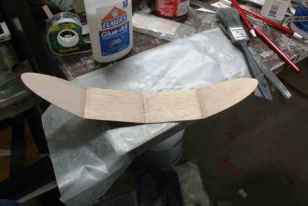
Construction began by locating the wing and gently sanding it in its balsa frame and then releasing it. Although the wing consists of 4 pieces, they are not yet cut apart at this stage. The only thing that marks the discrete pieces is a line.
With the wing remaining in one piece at this point, the instructions gave two options for shaping. The first was to merely round the edges of the balsa and I was sorely tempted to go this route. The other was to try and sand an airfoil into the wing. Nothing ventured, nothing gained.
In effect, I merely rounded the forward and outside edges but I made an attempt to approximate an airfoil on the trailing edge. I drew a sanding block across the rear edge from one end to the other trying to guide the profile down to a blade. It turned out better than I expected but it is certainly nothing to brag about.
The wing sections were numbered from left to right for later identification. A steel ruler was then used to guide
a razor knife along the marked lines and separate the wing into 4 segments. The freshly cut edges of the wing segments
were then beveled with sandpaper so that when canted, they would fit together better.
The kit came with the pieces to construct a pair of balsa jigs to aid in getting the correct dihedral angle on the wings. They were removed from their parent material and glued together. They are identical except for one being a bit taller than the other. After use, they are discarded so there are no extra points for style here.
 A piece
of wax paper was taped down to the working surface and then the inner right wing segment was taped flat to it. The tip
of the outer right wing segment was then taped to the taller of the two jigs. With that done, a bead of white glue was
run against the beveled edge and the two segments were pressed into place, allowing the jig to hold the pieces at the
correct angle. A day later, the jig was removed and the end piece did not fall off. I took that as a good sign. The
process was then repeated with the left side of the wing with similar encouraging results.
A piece
of wax paper was taped down to the working surface and then the inner right wing segment was taped flat to it. The tip
of the outer right wing segment was then taped to the taller of the two jigs. With that done, a bead of white glue was
run against the beveled edge and the two segments were pressed into place, allowing the jig to hold the pieces at the
correct angle. A day later, the jig was removed and the end piece did not fall off. I took that as a good sign. The
process was then repeated with the left side of the wing with similar encouraging results.
 The two
wing halves were then joined together in a similar manner. One side was taped down flat and the other was glued into
place using the shorter of the jigs positioned under the outer joint of the untaped wing. After another day to dry, the
jig was removed and things were still looking encouraging.
The two
wing halves were then joined together in a similar manner. One side was taped down flat and the other was glued into
place using the shorter of the jigs positioned under the outer joint of the untaped wing. After another day to dry, the
jig was removed and things were still looking encouraging.
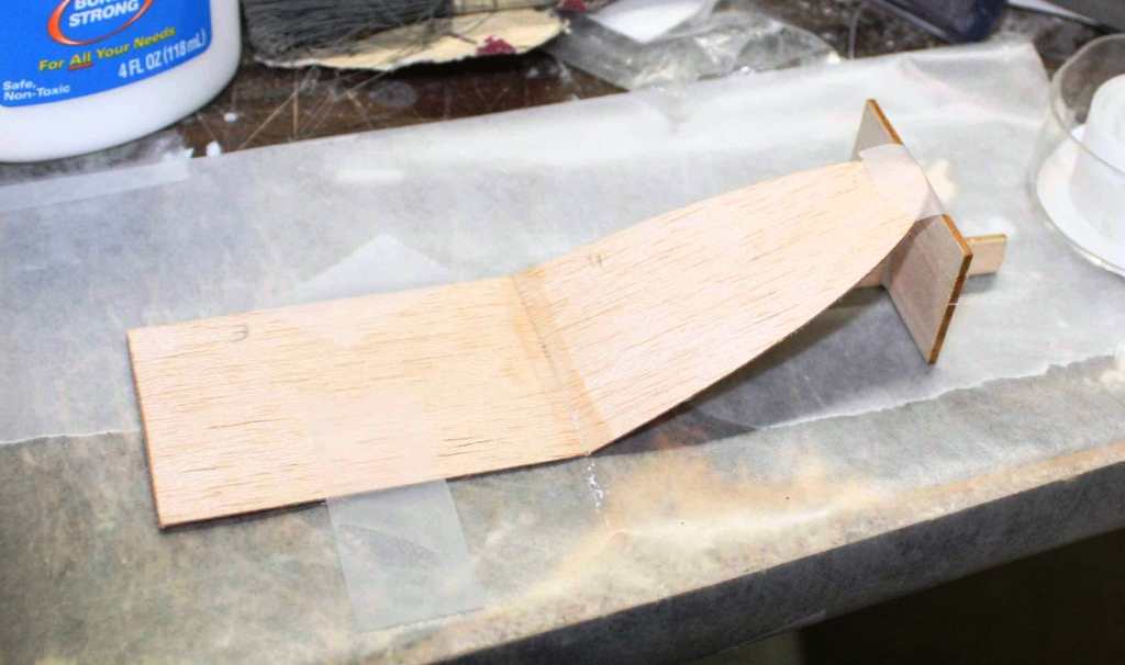
The tail boom comes in two main pieces. They were removed from the parent material and test fitted together. The fit was good and no sanding was needed. Some white glue was then put into the keyed joint and the two pieces put together and laid flat on the wax paper. A steel ruler was used to make sure the boom was straight. The next day, the boom was ready to be peeled up and looked fine. The jinx, if not gone, had certainly gone into hiding.
There are two balsa strips, rounded at one end, intended to be applied on either side of the forward end of the
boom. They provide some support on the side for the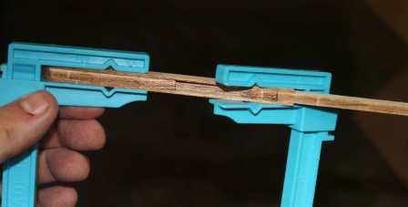 booster pod. A light layer of glue was applied to the boom and spread
out for the length of the facing. A facing was then pressed into place so that it was even with the front edge and the
top and bottom surfaces. It was allowed to dry like that for about 30 minutes. Some cheap plastic clams were used to
keep it in place. When dry, the opposite facing was placed in the same manner, clamped and set aside to dry.
booster pod. A light layer of glue was applied to the boom and spread
out for the length of the facing. A facing was then pressed into place so that it was even with the front edge and the
top and bottom surfaces. It was allowed to dry like that for about 30 minutes. Some cheap plastic clams were used to
keep it in place. When dry, the opposite facing was placed in the same manner, clamped and set aside to dry.
The horizontal stabilizer was removed from its sheet. Sandpaper was used to round all the edges. The vertically stabilizer was similarly removed and sanded on all edges except for the bottom, which was left flat.
With the tail pieces sanded and test fitted, a line of glue was applied to the base of the vertical stabilizer and it was fit onto the horizontal. The assembly was then set flat on the wax paper and a steel ruler was used to insure a right angle.
 After
drying for a day, the boom was unclamped and examined. It seemed in good shape and the pieces were mostly in alignment.
A bit of light sanding took care of evening up the edges. With the edges even, I then needed to taper the leading and
trailing edges of the facings on each side. I used a sanding block and tried to gently take the material down to a
knife edge.
After
drying for a day, the boom was unclamped and examined. It seemed in good shape and the pieces were mostly in alignment.
A bit of light sanding took care of evening up the edges. With the edges even, I then needed to taper the leading and
trailing edges of the facings on each side. I used a sanding block and tried to gently take the material down to a
knife edge.
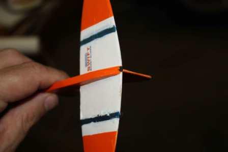
The tail assembly was placed at the end of the boom on the flat side. I had a sinking feeling about this because no jig or template was provided, only an admonition to make sure it was placed straight. I used white glue and eyeballed it the best I could and checking the angle with a steel ruler. I tried to make sure that it was straight and level. The feeling of impending doom was palpable.
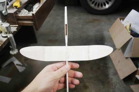
The next day, it was time to place the wing. A mark was made 1/2" back from the side pieced and the wing was
glued into place with white glue. The trepidation factor was even higher than with the tail because I know from
experience t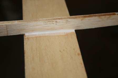 hese things just never turn out, especially when there is an angled surface involved. The feeling of
impending doom returned with a vengeance.
hese things just never turn out, especially when there is an angled surface involved. The feeling of
impending doom returned with a vengeance.
Even though I knew I was doomed by this point, I figured I had gone too far to back out now and I got to work on the pod hook. It was in two pieces which needed only to be glued together. I used white glue and clamped it.
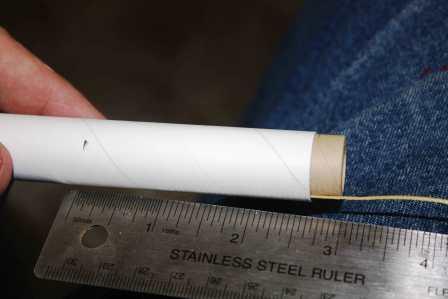 The first
step in working on the engine pod was to take the motor spacer and mark off 1/4". The thrust ring was then located
and the Kevlar®
was tied around it. A ring of white glue was swabbed around the interior of the motor tube, using the motor spacer to
mark the swab at the right depth. The spacer was then used to push the thrust ring into place, up to the mark which had
been made, and withdrawn. The motor tube was then marked for the placement of the engine hook and a slit was made in
the body tube to receive it. The hook was placed and a cardboard sleeve was slipped into place to hold it in place.
The first
step in working on the engine pod was to take the motor spacer and mark off 1/4". The thrust ring was then located
and the Kevlar®
was tied around it. A ring of white glue was swabbed around the interior of the motor tube, using the motor spacer to
mark the swab at the right depth. The spacer was then used to push the thrust ring into place, up to the mark which had
been made, and withdrawn. The motor tube was then marked for the placement of the engine hook and a slit was made in
the body tube to receive it. The hook was placed and a cardboard sleeve was slipped into place to hold it in place.
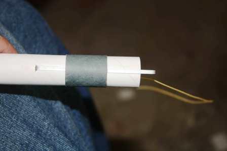 Shortly
after I began this build, Sheryl from Semroc contacted me and let me know that in some of these kits, the band was too
tight and gave advice of fixing the problem. Mine was just a touch tight but, in my mind, well within tolerances. It
was glued in place with white glue and filleted fore and aft.
Shortly
after I began this build, Sheryl from Semroc contacted me and let me know that in some of these kits, the band was too
tight and gave advice of fixing the problem. Mine was just a touch tight but, in my mind, well within tolerances. It
was glued in place with white glue and filleted fore and aft.
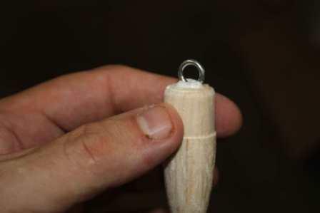
The nose cone was typical, high quality Semroc. I doused it with some thin CA to harden it up some.
 I turned
my attention back to the glider again. As far as I could tell by looking at it, it was in pretty good shape. The
intersections needed some filleting and I tried using Titebond Trim and Molding glue. It applied as good as I had heard
it would and when I checked back a day later, I was impressed.
I turned
my attention back to the glider again. As far as I could tell by looking at it, it was in pretty good shape. The
intersections needed some filleting and I tried using Titebond Trim and Molding glue. It applied as good as I had heard
it would and when I checked back a day later, I was impressed.
The pod hook was glued into place on the motor tube opposide to the engine hook using white glue.
The nose cone was lightly sanded and then the eye screw was screwed into place, backed out, the hole filled with white glue and screwed back into place.
The launch lug was glued into place along the pod hook with white glue. It was seated on top of the engine hook band.
 A
length of sewing elastic provided with the kit was tied to the eye hook and the Kevlar®.
The streamer was then secured into place halfway along the elastic with the provided adhesive strip.
A
length of sewing elastic provided with the kit was tied to the eye hook and the Kevlar®.
The streamer was then secured into place halfway along the elastic with the provided adhesive strip.
With that the pop pod was done and the rocket was ready to be finished.
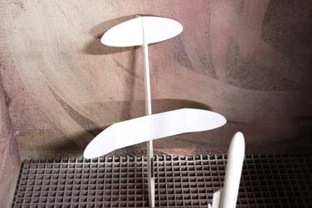
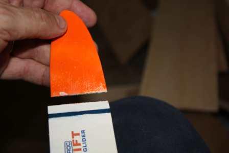
Before I could get started on the finishing, though, curiosity got the better of me and I had to try and hand toss the glider. I took it outside, turned into the wind, gave it a toss...and was flabergasted.
IT FLEW!!!!!!!!!!
IT DID NOT CRASH !!!!!!!!!!!
I grabbed Toby, gave him the camera and made him try and shoot a video.
I launched it again and it flew again, this time making a sharp left turn soon after launch. The video is here.
Since the glide was not really captured, we tried again, this time with me tossing towards the camera. It seemed to go well until a rocket beating tree got in on the act. Who would have expected the thing to go UP? The second flight can be seen here.
There was no damage and I had to try again. This time it still flew, or glided, but made a hard right turn. I put it down to the vagaries of the wind eddies around the corner of the house. The third video can be seen here.
I also realize that finishing will likely change the glide characteristics but at this point I don't really care: a glider I had built had actually glided. That had never happened before.
Finishing:
The instructions warn that finishing of this rocket should be done with a light touch in order to minimize weight.
All well and good but competitive performance to me took a back seat to just working and looking acceptable. On most
projects these days I use Elmer's filler but for this one I went with Balsa fillercoat on the theory that I would be
using less of it.
 I
painted it onto the pod hitting the nosecone and the balsa hook. The glider was completely covered with the stuff. I
put it on thick figuring I would only apply a single coat, even though that would not completely fill the grain.
I
painted it onto the pod hitting the nosecone and the balsa hook. The glider was completely covered with the stuff. I
put it on thick figuring I would only apply a single coat, even though that would not completely fill the grain.
The fillercoat had a day to dry and then I went after it with #400 sandpaper. The grain on the balsa parts of the pod seemed to have been mostly filled. The pod was then brushed off and set up in the booth where it was given a heavy coat of Kilz.
The glider was likewise treated to a scrubbing with the #400 paper. While the grain seemed to have been filled better than I had expected, there was still some that escaped unfilled. The glider was then primed with Kilz as well.
A day later, the pod was sanded again. I was mindful of the warnings I had heard about building up too much sealer/primer/paint and went after it with 320 and then 400 sandpaper. When I was done, I had misgivings because it mostly still looked white. I could see grain and pencil marks, though. Knowing how fast Kilz covers things up, I figured that most of what I was seeing was the chalkiness of the balsa fillercoat. The pod was then taken back to the booth and given a single coat of gloss white.
The glider was sanded with similar results. There were still some nasty spots of grain but I sanded down to where
the wood was just starting to show through. The glider was then given a single coat of gloss white as well.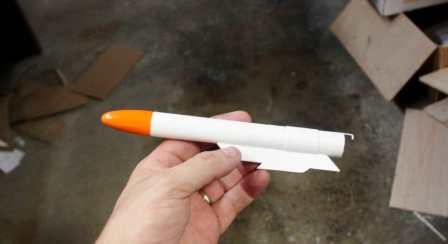
The next day, a ring of masking was applied just below the nose cone of the pod and foil was wrapped around the rest of the body. The nose cone was then sprayed a bright orange.
The glider was masked as well leaving the wing tips, boom and vertical tail assembly exposed for paint. The glider then had its date with the orange paint. This was done in 2 stages so that I would have something to grip.
 The
next day I peeled off the masking to take a look and It was looking good. That left only the blue striping and I took
out the tape to mask for a thin stripe on each wing and the the horizontal stabilizer. I then used a brush to place the
blue paint.
The
next day I peeled off the masking to take a look and It was looking good. That left only the blue striping and I took
out the tape to mask for a thin stripe on each wing and the the horizontal stabilizer. I then used a brush to place the
blue paint.
So far this project had gone extremely well; better than I had imagined it could with a glider project. Now was the time for tragedy to strike. It struck when I removed the masking and saw what had happened when the paint had wicked under the tape.
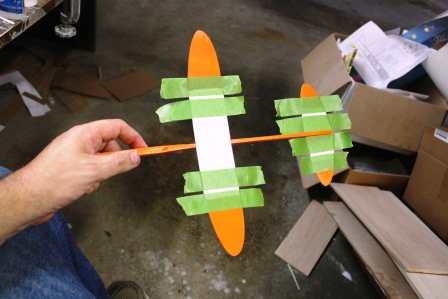
While I was stewing about the blue paint, I took the time to test fit the pod to the glider. It was a bit tight
due to paint having gotten in the hook cavity. I took a sanding stick and cleaned it out some until the fit seemed a
good one.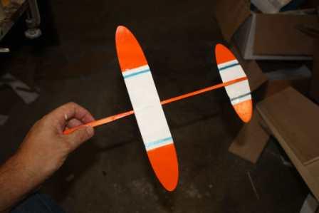
A day later, I was sure the blue paint had dried completely. I took some white acrylic and used a brush to try and cover up the worst of the bleeding. It certainly toned things down but it could probably stand another 2 applications in addition to the 2 that were put on.
The decals for the Swift are a simple matter but add a lot to the finished product. The largest of the decals has
the Semroc logo and the name of the rocket. I mounted it as on the face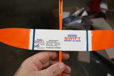 card; on the dorsal surface of the right wing. The kit also
came with a pair of smaller versions of the same design. These were mounted on the horizontal stabilizer, one on top
and one on the bottom, both on the right as you face the rocket. My kit also came with an additional decal identifying
is as production number 10 and having some more info about the rocket. I put this one on the left dorsal surface of the
main wing. That completed the "finishing" and, as I said, I thought even the simple decals added a lot.
card; on the dorsal surface of the right wing. The kit also
came with a pair of smaller versions of the same design. These were mounted on the horizontal stabilizer, one on top
and one on the bottom, both on the right as you face the rocket. My kit also came with an additional decal identifying
is as production number 10 and having some more info about the rocket. I put this one on the left dorsal surface of the
main wing. That completed the "finishing" and, as I said, I thought even the simple decals added a lot.
The first test "glides" after the finishing did not go well. The paint added plenty of weight and the Swift started to act like my Cosmos Mariner. I realized I needed tail weight.
A vid of the first post finishing crash can be seen here.
 The
second try is here.
The
second try is here.
I went inside and inserted one of the trim nails provided for weight into the left horizontal stabilizer and then went back outside to try again.
Adding one nail did not do too much to improve things although it did give me hope. I had one semi-successful glide before my nephew came out with the camera. Still, I thought it needed another nail.
The first test with one nail can be seen here.
The second test with one nail can be seen here.
The third test with a single nail is here.
I added another nail and did not do much better. And on the 3rd flight, it crashed in the street and broke off a wing tip.
The first try with 2 nails is here.
The second try with 2 nails is here.
The fateful thrid flight with 2 nails is recorded here.
I took the carcass back into the shop to try and get it fixed up again. The tip was put pack on with a double
glue joint using yellow glue. The angle was obtained by eyeballing it.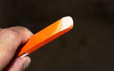
While repairing the wingtip, I noticed that bouncing on the asphalt also took a bite out of the nose. At first I was going to try and fill it but then thought better of that approach. I thought I might be able to reduce the nose weight a little bit by sanding a bevel into both sides of the nose. I took out a sanding block and got to work. The newly beveled nose was sprayed with orange paint and it blended fairly well with the rest even though the new surface had not been sealed.
 When
the glue from the wingtip repair had dried, I took out some Tightbond Trim and Molding glue and applied a fillet to
each side of the joint in an effort to strengthen it.
When
the glue from the wingtip repair had dried, I took out some Tightbond Trim and Molding glue and applied a fillet to
each side of the joint in an effort to strengthen it.
When the repairs were complete, I tried throwing the glider a few more times to test it out but the results were both contradictory and confusing. Sometimes it would stall like it needed more tail weight. Other times it would dive and a few times it just kind of moved without doing anything resembling gliding. In the course of one of these tests, it turned in a very nice glide that rivaled anything done by the unpainted model. I decided to just wait and try it out on the launch pad. I called the construction of this one done.
Construction Rating: 4 out of 5
Flight: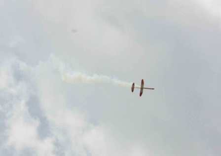
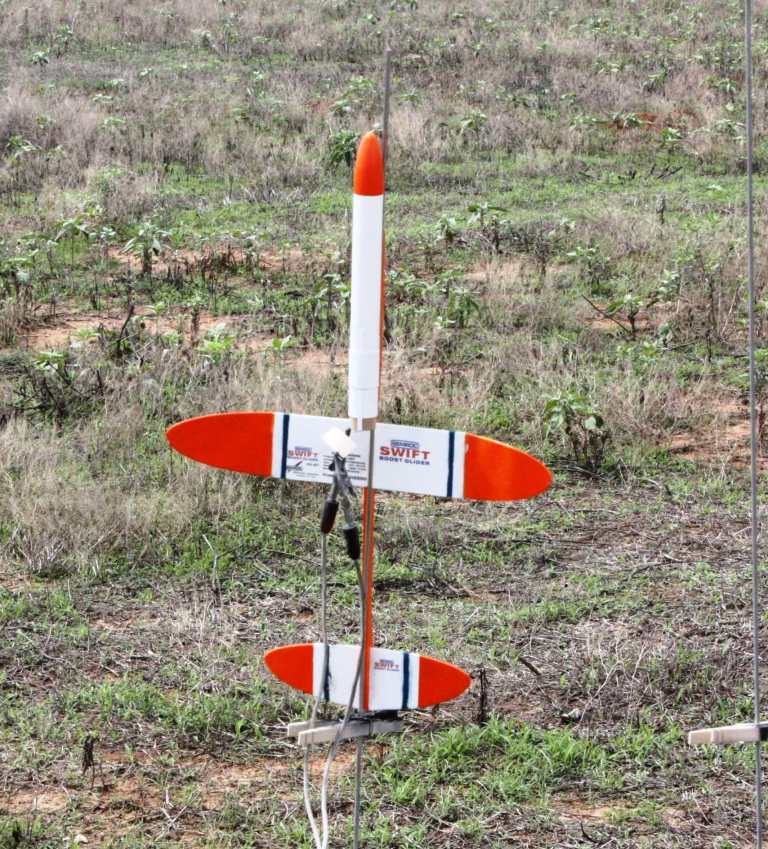
The maiden flight of the Swift Boost Glider was at the September 09 launch of the Alamo Rocketeers. I prepped it with
a 1/2A6-2 and set it up on the pad. It received favorable comments from all for appearance. Almost immediately after
leaving the rod, the rocket started to arc over but the curve became more gentle over time and it always had a slight
upward inclination. I had a good view of the pod popping off; that was fun to watch. Then I got to watch the glider
plummet to the earth; that was not fun to watch.
The vid of this event can be seen here.
 The
unanimous consensus of those present who knew about such things was that the glider was tail heavy. I pulled out one of
the nail weights and repacked the streamer in the pod realizing that I had forgotten to put any wadding in there the
first time. Fortunately, the streamer was only slightly singed. For the second flight I loaded a B6-2 since I had no
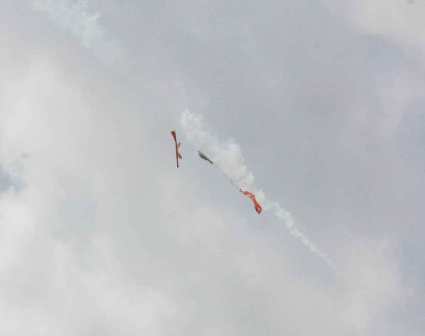
B4-2s. It was taken out to the pad and hooked up. When the ignition button was fired, the Swift showed the same arcing
behavior as before but not as drastic. It went up relatively high considering it spent most of the boost at about a 60
degree angle to the ground. When the pod popped, though, things were definitely different. It started gliding. It would
lazily turn into the wind and seem to just stand in place for a while not losing any altitude and maybe even gaining a
bit. It would then turn with the wind and fly away for a short time (but a long distance) before turning into the wind
to repeat the performance....again...and again...and again. On some circuits it did gain altitude but it was definitely
going to come down...eventually. I began to get worried that I would lose it but everyone kept an eye on it until it
finally went down...a long way away.
The
unanimous consensus of those present who knew about such things was that the glider was tail heavy. I pulled out one of
the nail weights and repacked the streamer in the pod realizing that I had forgotten to put any wadding in there the
first time. Fortunately, the streamer was only slightly singed. For the second flight I loaded a B6-2 since I had no
B4-2s. It was taken out to the pad and hooked up. When the ignition button was fired, the Swift showed the same arcing
behavior as before but not as drastic. It went up relatively high considering it spent most of the boost at about a 60
degree angle to the ground. When the pod popped, though, things were definitely different. It started gliding. It would
lazily turn into the wind and seem to just stand in place for a while not losing any altitude and maybe even gaining a
bit. It would then turn with the wind and fly away for a short time (but a long distance) before turning into the wind
to repeat the performance....again...and again...and again. On some circuits it did gain altitude but it was definitely
going to come down...eventually. I began to get worried that I would lose it but everyone kept an eye on it until it
finally went down...a long way away.
I wish I could show some great photos of the flight but I was to busy being awestruck to remember to take any. All I have to offer is a photo of the grounded pod a few yards from the launch pad. Oh and my daughter took this video: http://www.flickr.com/photos/23694991@N03/3960923315/
Flight Rating: 5 out of 5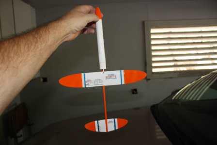
Summary:
I think Gliders are an acquired taste but this one is a great place to start doing the acquiring. It is my first and
only glider that can be termed a success to date. The construction was simple enough for anyone to do, the instructions
were well written and, most of all, it works.
Overall Rating: 4 out of 5
Other:
Persons wishing to follow the exploits of this rocket can do so here:
http://www.flickr.com/photos/23694991@N03/collections/72157621956600615/
Other Reviews
- Semroc Swift Boost Glider By Chan Stevens (October 10, 2009)
Brief: With the introduction of the Swift, Semroc has now added a conventional boost glider to their fleet, and one easy enough for even a nove modeler to build and get flying reasinably well. Based upon the 1969 Centuri design, this "retro repro" features laser-cut parts to speed up construction, as well as Kevlar ® /elastic shock cord on the pod to improve the ...
 |
 |
Flights
Sponsored Ads


|
|