Scratch Bio-Hazard Original Design / Scratch Built
Scratch - Bio-Hazard {Scratch}
Contributed by Jon Chrisman
| Manufacturer: | Scratch |
What a cool concept! People from all over the country(world) send in parts to a central location where one lucky individual opens, piles and then redistributes the parts to participants! The following is write up on my build in this contest. A rocket I have called Bio-Hazard!
The Parts
When I received my box of parts I eagerly opened it up and dumped out the contents! What a selection! Some strange stuff too! A SPOON!?!?!
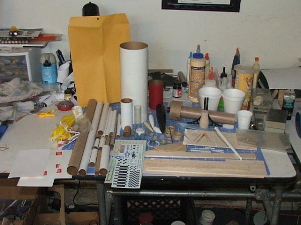
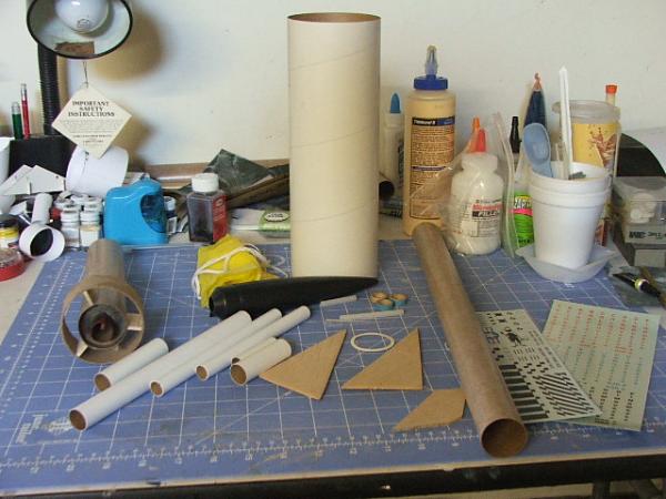
The following picture shows the parts I selected to make my rocket: .
The Build
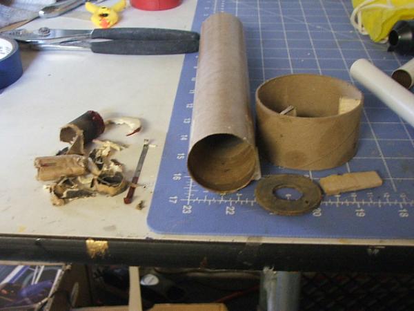
1: Before construction could begin, some destruction had to take place. After some preliminary tests using RocSim it was determined that this design would not fly on a single 18mm motor. The existing motor mount is taken out. Also the existing ring was removed to beef up the glue joints. The aft centering ring was destroyed in the process but the forward centering ring was salvaged to be used again.
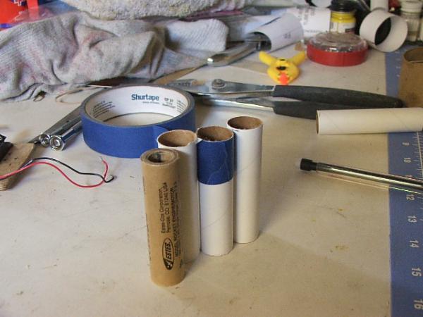
2: New motor mount tubes were then cut from the BT20 tube. This will be a 3x18mm cluster rocket. After the tubes were cut engine blocks were glued into the forward end of the tubes. .
3: The forward centering ring from step 1 is next glued to the base of the BT55 tubing making sure the tube is centered on the ring.
4: The 3 motor mount tubes are then glued together and dry fitted into the BT60 to hold the tubes together for the glue to fully dry. After the glue has dried the assembly is glued into the BT60 flush with the end of the tube. I then tore some paper from the shipping box and crumpled into small balls. Soaked with white glue these balls are then used to fill the gaps around the motor tubes. .
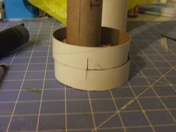
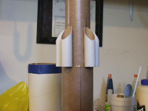
5: Next, the BT55 with the glued on centering ring is inserted into the BT60 until the centering ring is butted up to the front of the motor tubes. Then, the BT55-BT60 centering ring is slid down and glued flush to the end of the BT60 tube..Using 'Template Widget' a fin marking guide for BT55 with 5 fins is printed out and the tube is marked. The lines are extended for 3” along the tube.This is where 5 forward decorative tubes will go.
6: The tail ring is rebuilt using 5 minute epoxy. 2 1” lengths of the BT101 tube are cut. 5 2” long tubes were cut from the BT5 tubes. The fronts of the BT5's were cut at a 45 degree angle. . .
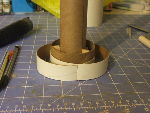
7: The tail ring is then glued to the base of the BT60.Next the 2 BT101 rings are stacked with one side on opposing sides of the tail ring tube. The cross pints of the BT101 tubes are marked and 1/2” long slits are cut so the rings can 'interlock'.
8: The BT101 tubes are now interlocked and glued to the tail ring tube.
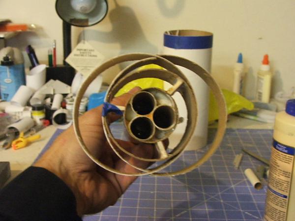
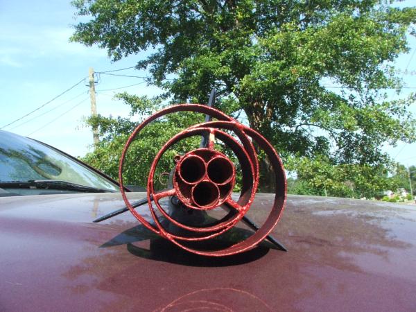
. And here is how it should look from the business end:
9: Next, the fins are glued onto the BT60 lined up with the tail ring stand offs. .
10: The 5 forward decorative tubes are now glued to the BT55 tube with the aft end of the tubes butting up to the BT60 tube.
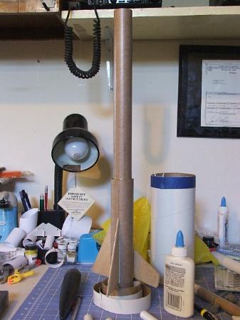
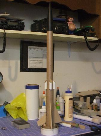
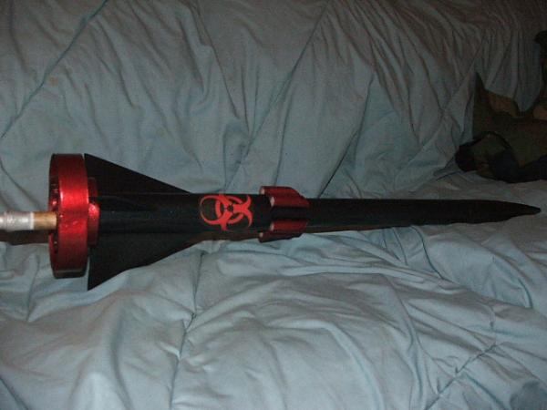
11. Placing the nose cone on your finished product should look like this. For stability issues with this being a cluster and the added weight at the aft end of the rocket, 1.5oz of ballast was added to the nose cone. Shock cord was mounted to the BT55 tube using the tried and trusted tri-fold method and tied to the nose cone. .
Finish
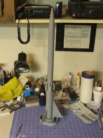
Since I wanted the finish on this rocket to stand out I went a little over board on the paint budget.. But I think the results are well worth the money spent..First step was in the prep and the first prep coat was the plain old gray primer to fill the grain and spirals..I applied 2 coats with light sanding after each coat. .
Next step was to apply the color prep base coat, which, unfortunately, I do not have a picture of..It was the Duplicolor Metalcast Prep silver under coat..I then applied 2 coats of Metalcast Red to the aft rings and the 'thruster' tubes. .
Next up was the overall color ..After some pretty intensive taping I applied Duplicolor Color Effex Black to the rocket..It turned out pretty well, but I wanted a little more 'punch' so I went one step further after this..I also applied a decal I had printed out of the Bio-Hazard emblem. .
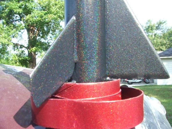
So, to make that little extra 'punch' I got some Duplicolor Clear Effex paint..This really took it over the top I think and the sparkles really show up great in the sunlight! .
Here is a close up to highlight the sparkles! .
Flights
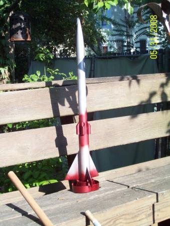
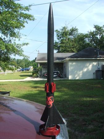
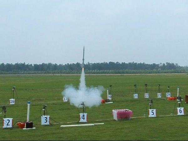
The first opportunity I had to fly Bio-Hazard was at NSL 2008..After running numerous simulations thru RocSim it kept indicating that the motor that would achieve the lowest DV(Deployment Velocity) was with 3 Quest C6-3's. As I didn't have any, I purchased a pack on site and flew it..Deployment was just before apogee with a successful soft landing. And here it is leaving the pad:
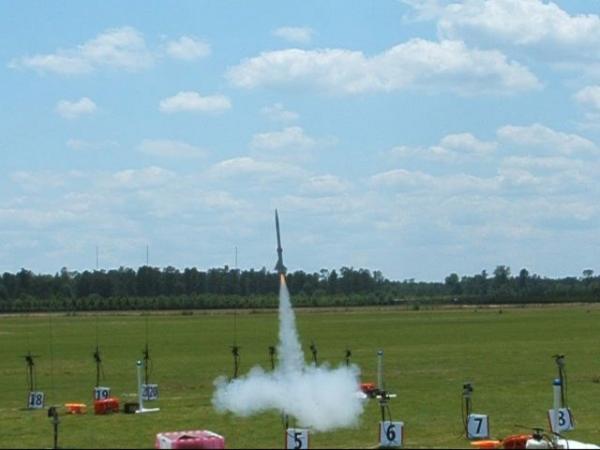
After the first flight was a success the next day(Sunday), I went ahead and put 3 Estes C6-5's in it and flew it again! Again, a successful flight with deployment just a little past apogee..Here is a frame from the 2nd flight as it clears the pad: .
Sponsored Ads


 |
 |