Descon Mark's Glider Launcher
Scratch - Mark's Glider Launcher {Scratch}
Contributed by Mark Recktenwald
| Manufacturer: | Scratch |
(Contributed - by Mark Recktenwald)
 CONCEPTION & DESIGN NARRATIVE:
When out shopping, I usually scan the toy isle looking for Bail Out payload
candidates. Most of my kids' (boys 7 & 9) action figures tend to hang up in
the Bail Out's BT-60 inside diameter of 1.595" (41 mm). A couple of months
ago, while at my local Big Lots, I saw these little foam gliders. They are
packed two to a card for $0.99. I figured there had to be a way to launch and
eject these things and have them glide back down. The kids ought to get a kick
out of the little gliders looping through the sky.
Without any idea of what to use to launch them, I didn't buy them. I was in the middle of a scratch built sport scale (1:154) Saturn V at the time and didn't want to start something new. Once the Saturn V was done, I started thinking of the gliders for my next project.
The gliders are called Super Tuff Mini Shots Stunt Gliders. They are made in China for Just Toys, Inc. of New York, NY. They are intended to be used in Mini Shots guns. These appear to be comparable to the Nerf guns that shoot mini darts.
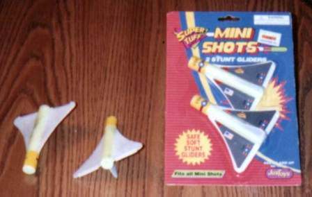 The body of the glider is yellow
foam, approximately 0.67" (17 mm) in diameter, 4 3/8" (111 mm) long,
with a 3/16" (5 mm) diameter hole up the back. The glider has white foam
semi-delta wings, similar in shape to the Space Shuttle; approximately 3"
(76 mm) at the root edge and 1 3/4" (44 mm) at the trailing edge. The
delta-shaped tail rudder has a 1 7/8" (48 mm) root edge and a 3/4"
(19 mm) trailing edge. The rear of the wings and rudder are cut longitudinally
and crimped 3/16" (5 mm) from the trailing edge to create moveable control
surfaces. A few minutes spent with each resulted in relatively flat spiral
flights that will stall, drop a bit, and spiral some more.
The body of the glider is yellow
foam, approximately 0.67" (17 mm) in diameter, 4 3/8" (111 mm) long,
with a 3/16" (5 mm) diameter hole up the back. The glider has white foam
semi-delta wings, similar in shape to the Space Shuttle; approximately 3"
(76 mm) at the root edge and 1 3/4" (44 mm) at the trailing edge. The
delta-shaped tail rudder has a 1 7/8" (48 mm) root edge and a 3/4"
(19 mm) trailing edge. The rear of the wings and rudder are cut longitudinally
and crimped 3/16" (5 mm) from the trailing edge to create moveable control
surfaces. A few minutes spent with each resulted in relatively flat spiral
flights that will stall, drop a bit, and spiral some more.
The first idea for a launch vehicle was a large diameter rocket with the gliders ejected from within the body tube with the parachute. With the glider's approximate 4" (100 mm) wing span, this was quickly ruled out.
The second idea was "strap-ons" with an ejection-triggered strap release. I considered a slotted main tube with straps connected to some type of piston assembly, but that seemed too complicated. I started playing around with pieces-parts I had left over from an Estes Designer's Special box. I found a 4 1/32" (103 mm) piece and a 12 5/8" (320 mm) piece of BT-50. These looked good together with the short piece at the bottom. The I.D. of BT-20 at 0.710" (18 mm) looked like a good size for the straps and the holes in the rear of the glider looked like they could be used to retain the rear end of the glider. There was a 4 1/8" (105 mm) long PNC-50 in the Designer's Special box, and two 2 7/8" (73 mm) long PNC-20s. The base airframe was set.
The first drawn design had two small balsa tabs on opposite sides at the bottom end of the lower (short) section to engage the 3/16" (5 mm) holes of two gliders. Two sections of BT-20 would be glued to opposite sides at the lower edge of the upper (long) section. The BT-20 straps would be topped with PNC-20s. I reconsidered the use of the PNC-20s. These appear to be the same as used in the Tornado (Estes # 2004) which I still wanted to scratch from the kit. I next considered card stock fairings. A few days later I figured, heck, untopped straps will virtually guarantee separation while a capped tube may create a little vacuum and delay or prevent proper separation. The straps were sized at 3/8" (10 mm). I don't know why other than they looked good.
I know what you're thinking: "Hey, this looks just like the Estes A.R.V. Condor" (Estes #2075). It is similar, but this is cheaper than the A.R.V. (US $13.29 list), plus there is a local source for cheap replacement gliders. Big Lots has a ton of these.
The first stability check was run in VCP. The noses of the gliders were treated as a transition section. The glider body cross-sectional areas and the airframe cross-sectional area were summed. An effective diameter was calculated based from this sum. The glider wings were entered as 4 delta-shaped fins. The tail rudders were ignored. The first run showed a center of pressure (CP) about 3/4" (19 mm) below the front edge of the gliders. This looked good.
Even though the CP looked good, I was concerned with the lack of fin area along the axis through the gliders (perpendicular to the gliders’ wings). The relatively small tail rudders were the only "fins" in this axis. To add fin area in this axis, the small balsa tab idea was turned into a flat-top fin like this:
This configuration wasn't analyzed in VCP, but it has to be better (lower CP).
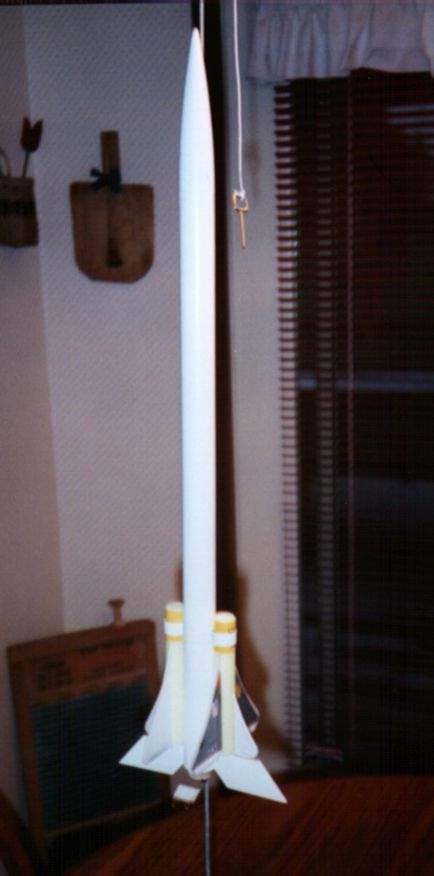
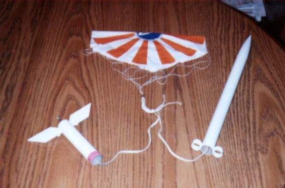
The final configuration is shown in the photographs below:
PARTS LIST (as-built, see SUGGESTED
MODIFICATIONS below):
Lower Section:
4 1/32" (103 mm) BT-50
Standard Estes Engine Mount (18 mm)
3/32" (2.5 mm) Balsa Fin Stock (see pattern above)
2 3/8" Launch Lug
1" (25 mm) TC-50 - glue with one-half projecting from top of BT-50
Standard Estes Shock Cord Mount
18" (460 mm) x 1/8" (3 mm) Elastic Shock Cord
Upper Section:
12 5/8" (320 mm) BT-50
Two 3/8" (10 mm) BT-20 - glue to opposite sides of lower edge of BT-50
Standard Estes Shock Cord Mount
18" (460 mm) x 1/8" (3 mm) Elastic Shock Cord
12" Plastic Parachute
4 1/8" (105 mm) long PNC-50
Gliders:
Two Just Toys Super Tuff Mini Shots Stunt Gliders*
*These are available at Big Lots or E-mail me if you want me to buy them and
ship them to you.
- Tie Shock Cords (SC) together, leave a loop.
- Attach 12" parachute to loop in SC using locking snap swivel.
- Fold & roll parachute, wrap lines around.
- Pack most of SC into upper section, then parachute.
- Loosely crumple 4 squares of recovery wadding, place 3 in upper section, 1 in lower section.
- Join upper and lower sections, rotate until Launch Lug (LL) is near one of the BT-20 straps.
- Hold rocket nose down, insert gliders nose down into straps.
- Rotate lower section until fins are aligned with center of straps.
- Push Gliders up onto tabs (engage tab on fin into hole in glider) and hold.
- Return rocket to an upright position.
- Insert prepped engine.
- Place rocket on launch pad.
- Align rudder fins on gliders with fins on lower section of rocket.
- 5...4...3...2...1...WHOOSH!
Date: October 22, 1998
Time: 1815
Temperature: 45-50 °F (7-10 °C)
Wind: NW, 5 mph, gusting to 10 mph
Engine: A8-3
Results:
- Vertical flight to 200 or 300 feet above ground level (AGL).
- Ejection/separation occurred just past apogee.
- One glider nose-dived, found about 100 feet down wind from the launch pad with one wings separated cleanly at its glue joint to the glider body, could be a victim of SC recoil and impact.
- Rocket descended quickly to about 100 feet AGL before chute began to unfurl.
- At about 40 feet AGL, chute was fully inflated; rocket landed about 100 feet down wind from the launch pad.
- Second glider spiraled slowly down and was found about 200 feet down wind from the launch pad.
- Slight scorching on bottom sides (side toward rocket body) of the gliders.
- Severe scorching on lower 2" (50 mm) of SC on lower section of rocket.
- Lengthen lower section 1/2" (13 mm) and square off the lower inside corner of the fin. I can see mine breaking off later. This will double the length of the glue joint.
- Use a more flame resistant material for a SC in the lower section. This piece could be stainless steel or Kevlar®.
- Lengthen the lower section to move the ejection/separation point up and lengthen the BT-20 straps; allow the straps to hang down below the separation plane. This will protect the gliders from scorching.
- Use two chutes or streamers and disconnect the two body sections for dual recovery. This will eliminate SC recoil and associated glider damage.
- Sweep the fins and add small swept fins perpendicular to them to allow the rocket to stand without a support rod. This makes it easier to display.
Lower Section:
5 1/2" (140 mm) BT-50
Standard Estes Engine Mount (18 mm) 3/32" (2.5 mm) Balsa Fin Stock (click here to see pattern)
2 3/8" Launch Lug
1" (25 mm) TC-50 - glue with one-half projecting from top of BT-50
Shock Cord Mount compatible with chosen material on next line
Flame Resistant Shock Cord (stainless steel, Kevlar®, etc.)
Upper Section:
12 1/2" (317 mm) BT-50
Two 1" (25 mm) BT-20 - glue to opposite sides of lower edge of BT-50 with one-half projecting below the lower edge
Standard Estes Shock Cord Mount
18" (460 mm) x 1/8" (3 mm) Elastic Shock Cord
12" Plastic Parachute
4 1/8" (105 mm) long PNC-50
Gliders:
Two Just Toys Super Tuff Mini Shots Stunt Gliders
| |
|||
| SUGGESTED ENGINES: | (feet) | (meters) | |
| A8-3 | 200 | 60 | |
| B4-4 | 500 | 150 | |
| B6-4 | 400 | 125 | |
| C6-5 | 700 | 200 | |
| D12-5* | 1000 | 300 | |
My name is Mark Recktenwald. I used to fly rockets as a kid (between 11 and 15), and started up again about 8 years ago. It has only been since June of this year that I have really gone "hog-wild" over rockets with my 7 and 9 year old boys. You may recognize my name from RMR. I usually post under "kentengr@raex.com".
This page was created on October 31, 1998.
Sponsored Ads


")

")
 |
 |