| Manufacturer: | Scratch |
 Rattworks 29mm motors are fun to fly, but have two challenging aspects that need to be addressed when designing a rocket to use them. The motors are very long (H70: 18", I80: 29" and I90: 36") and have a relatively low thrust. The typical way to design a rocket for these motors would be to make the rocket very long and skinny with the usual motor/parachute/electronics bay stackup. This results in a very high flying rocket that is not appropriate for many east coast launch sites with relatively small flying fields. However, the only real constraint is to make the rocket light enough for it to get up to speed off of the rod/rail. The parachute and recovery electronics could go anywhere.
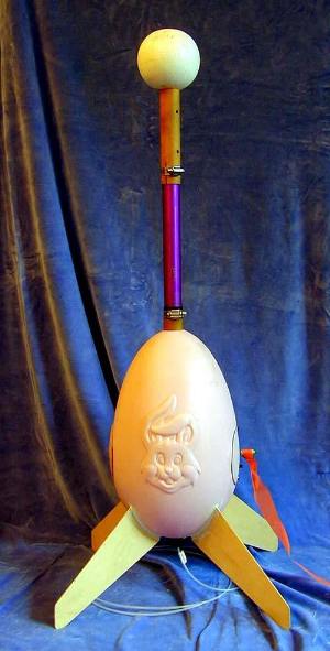
A couple of Easter's ago, I was in K-mart and found some big plastic easter egg (~8" diameter) on sale for a few dollars each. These looked like they had distinct airframe possibilities, so I picked up one of each color. They ended up being perfect hybrid rocket airframe candidates since they were lightweight and had a good diameter for plenty of drag to keep the rocket relatively low, even under I power.
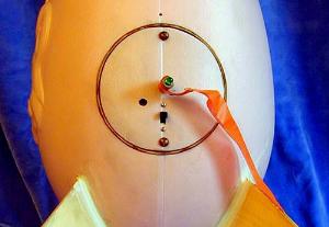
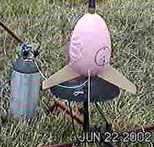
One additional problem with designing for a variety of hybrid motors is the large difference in length between the motors and finding a way to vent each one. My solution here was to split the rocket in two. The bottom will be the egg/fin/electronics and parachute. The top will be the ballast section to keep the CG forward. Thus, the rocket length will be dependent on the particular motor flown that day. As seen in the above picture, about 1 foot of the rocket length is bare I80 motor.
Construction
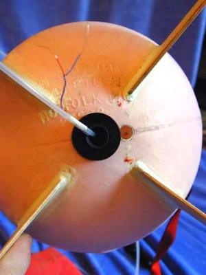
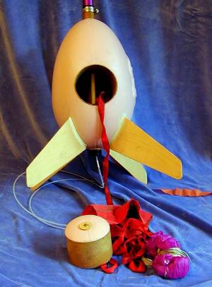 The bottom easter egg section is composed of 29 mm phenolic motor and 4" phenolic body tubes intersecting at a 90 degree angle. One end of the 4" tube is the electronics bay hatch and the other end is the "nose cone" where the parachute is ejected from. It was challenging finding the right place to cut the holes for these tubes since the egg was not quite symmetric.
I first located the holes for the 29 mm motor mount by a bit of trial and error. I twirled the egg on two pins pressed into the top and bottom of the egg until the egg turned relatively evenly. The holes for the 29mm motor tube were then drilled with a hole saw. The 4" holes were cut using an Olfa circle cutter, keeping the cutouts. These holes were located at the widest portion of the egg by measuring a a constant distance from the bottom along the two seam lines. The hard part turmed out to be cutting the 29 mm holes in the 4" tube since they had to align with the holes in the egg as well. My first try was almost right, but I ended up being off by about 1/4 inch that I compensated for by elongating the upper hole in the 4" tube. Once these fit, I epoxied a length of 5/16 " ID polystrene tube along the length of the motor tube as a launch lug. This motor tube assembly and 4" body tube were then epoxied together and to the egg with 15 minute epoxy. CA was used to glue the 4" tube to the Egg. I used a dremel tool with a sanding drum to trim the 4" tube flush with the egg. The 29 mm tube was left extending out about 1" through the front and 1/4" out the back.
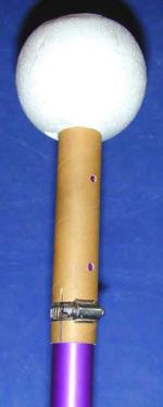
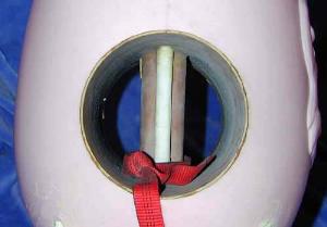
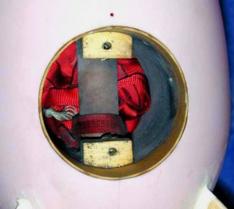
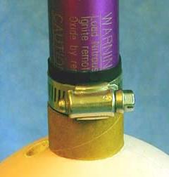 The ballast section was made with a 29mm motor tube section epoxied into a 4" styrofoam ball. About 5 oz of lead shot was epoxied into the forward section of this motor tube section to bring the CG forward. 5/16" ID polystyrene tubing was inserted through the foam ball along the length of the motor tube to allow the launch rod to slide through. 1/4" holes were drilled into the side of the motor tube for nitrous venting. The lower section of the tube was slotted to allow the tube to be clamped to the motor mount with a small hose clamp. There is some clear space between the top of the motor and the top of the motor tube. This serves as a shock absorber when the rocket lands. A 2" piece of bicycle tubing is slipped over the motor and slid down to the front of the egg section to keep the lower hose clamp from scratching the motor, as well as for motor retention.
The electronics bay is a 4" coupler with a bulkhead epoxied into the back. Two small plastic tubes were added near the top and bottom of the coupler to allow the bay to be bolted into the rocket. Two small wooden blocks were epoxied into the top and bottom of the 4" body tube with T-nuts installed to anchor the electronics bay bolts. Two long brass bolts hold the bay into the airframe.
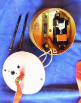
Hybrid motors have no ejection charge themselves, so electronics must be used. There is no "clean air" in this design so that an altimeter may not function properly. I used a magnetic apogee detector to deploy the parachute, which can be seen in the above picture, next to the 9V battery. The on/off switch and ejection charge shunt/test LED are bolted into the plastic cover. The ejection charge is attached via a small terminal block screwed into the opposite side of the bulkhead.
The "nose cone" is made from a 4" coupler section, a circle of 3/4" pink foam insulation and the other plastic circle cut from the egg. A short brass bolt through 1" circles of plywood hold the "nose cone" together. On the first flight, these circles were omitted and the bolt pulled through the plastic and foam at ejection. About 10 ft of 3/8" tubular nylon webbing was used as the shock cord which was looped around the motor tube for a very secure shock cord attachment point. A 40" parachute protected by a nomex heat shield completes the recovery section
 The fins were cut from thin aircraft plywood. The shape was chosen to basically so it looked good, but with significant span and leading edge sweep. This would get the fins to extend well away from the body and give a good contribution to the CP. The approximate dimensions are:
2" tip, 7" leading edge sweep, 4" root and a 7" span. These were epoxied to the motor tube through slots cut in the egg. When the epoxy was cured, I added fillets made from PC-7 epoxy paste. Given their size, the fins seem pretty sturdy.
Sometimes people worry about fins extending beyond the back of the rocket breaking during landing. I didn't have to because of the parachute attachment point and forward weight distribution which makes the rocket land nose first.
Where's the CP?
This is an different looking rocket but was modelled with VCP. The CP is at about at widest part of egg. The lead weight in the forward styrofoam ball was chosen to put the CG about 8" in front of CP with the H70 motor.
Flight Log
On the pad with a Pratt Hobbies RTLS system.
This rocket has been launched about 6 times. It jumps off of the pad quite quickly since it only weighs about 3.25 pounds (including weight of I80 motor). I enjoy watching this rocket since there is virtually no smoke and you can watch it ascend even from directly below. The Hybrid Easter Egg is a nice, stable flier but there have been 3 minor incidents. On the first flight, the shock cord attachment bolt pulled through the "nose cone", but this was strengthened with some small wooden disks . Another time the parachute ejected near motor burnout. I'm not sure why, but it was possibly due to motor vibration and low air pressure outside the convex section of the rocket pulling off the "nose cone". I added a bit of masking tape to make it a tighter fit and this hasn't happened again. One hard landing at NYPOWER2002 knocked a fin loose but that was easily reattached with epoxy.
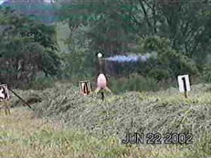
The following are video stills from the CTRA/NARCONN June 22 launch in Cobleskill, NY on an I80.
Nitrous venting and liftoff.

The signature upside-down recovery.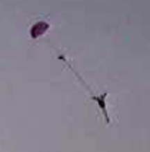
Sponsored Ads


![Vintage Estes Viper #0820 Model Rocket [4*G-17.25]](https://i.ebayimg.com/thumbs/images/g/Q7EAAOSwN1Nl1kDF/s-l225.jpg "Vintage Estes Viper #0820 Model Rocket [4*G-17.25]")


 |
 |