| Construction Rating: | starstarstarstarstar_border |
| Flight Rating: | starstarstarstarstar_border |
| Overall Rating: | starstarstarstarstar_border |

Brief:
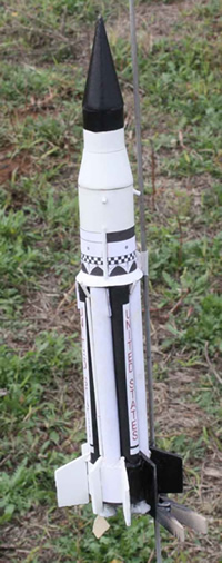
Scale, 18mm, Parachute Recovery
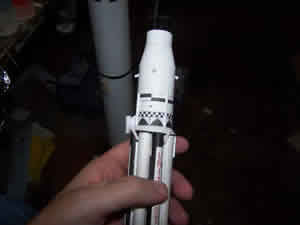
Of all the Dr. Zooch line, The Saturn I SA-5 is the one that most appeals to me, mainly because it is different from everything else. I'd had it for a while but did not start on it immediately because I wanted to get a few Zooch kits under my belt first. I survived the building of the Little Joe LES and actually enjoyed building it so I figured it was time.
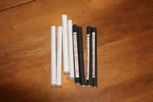
I know that Dr. Zooch packs a lot of rocket in those little boxes of his but I was unprepared for just how small the rocket actually is. That does not detract from the quality; it is merely an observation.
Construction:
The first step in the instructions is to do some painting. The balsa nose cone and transition needed to be painted white as did the various body tubes. I wanted this one to look good so I pulled out the Elmer's filler and applied it and set the parts aside to dry.
While the goop was drying, I got to work on the motor mount. The motor tube is set up along a butt mounted marking guide to transfer 8 marks evenly around the tube. An angle was then used to extend the lines. With the lines transferred, I measured back the proscribed distance and made a narrow slit for the engine hook. The hook was then put into place.
The kit has three centering rings. Two have notches to accommodate the engine hook at the aft end and the other is plain. The instructions make a point of saying how critical the distances are. The rearmost goes an 1/8" from the end of the tube. The forward most goes 5.5" from the middle tube. The problem is the location of the middle tube. The text gives 1/4" and the illustration gives 1/2". I settled for taping the engine hook in place and posting a question for Dr. Zooch on TRF.
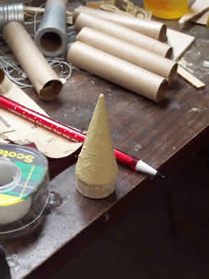
After a day of drying, I took some sandpaper to the balsa parts and started to sand. The result was fairly smooth and I was satisfied with it. With the balsa sanded, I now needed to paint the parts. In addition to the balsa and the tubing, 4 small wooden downs and one larger one were set up in the spray booth and painted a gloss white. Two coats were applied.
I heard back from Dr. Zooch in short order and learned that the instructions should say that there should be a 1/2" gap between the rearmost centering rings. Armed with that bit of wisdom, I glued the second ring 1/2" from the rearmost and the third one 5.25 inches forward of that. They were placed with yellow glue and fillets were run around both sides of all rings. The rings were also carefully checked to make sure that they were straigt.
While the glue on the rings was drying, I turned my attention to the spider beams used to algn the tanks. Using the template provided, 8 were cut from a sheet of balsa material. White glue was then used to place them along the lines drawn on the motor tube. In short order, all 8 were in place and the assembly was set aside to dry.
The next day, with the glue on the spider beams presumably dry, I put the motor mount assembly into the booth and
shot it with black.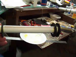
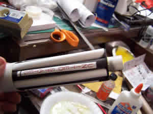
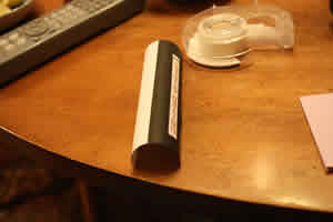
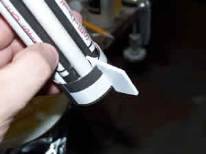
As the black paint was drying, I began the process of cutting out the LOX tank and fuel tank wraps. These were rolled on a rubber mat with the forming dowel to help the forming of the tubes.
Also, in a fit of idiocy. I went ahead and installed the lower tube before installing the tanks. This posed a problem later on but was not insurmountable. To install the tube, I just sanded the rings a bit and then swabbed some white glue to the inside of the tube. The motor mount was slid in until the aft ring was flush with the end of the tube.
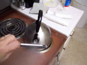
IN accordance with some advice from Dr. Zooch himself, I decided to try and use live steam to help the forming of the tanks. I set a teakettle on to boil and left the little whistle thing on the spout in place. When the water boiled, it channeled the steam in a stream. Steaming the tank cutouts did help to get them rolled tightly.
Unfortunately, although the steaming helped, I did not get the tanks rolled tightly enough. I also did not get them straight enough. When I installed them into position, the result was visually embarassing. Worse, they did not completely fit below the forward centering ring. I had a helical, ugly mess.
My mess resulted in some soul searching and sporadic depression but Dr. Zooch came to the rescue with the offer of some more tank wraps. O desperately wanted to PURCHASE the said wraps but he would have none of it and insisted on sending them to me. I suppose his having just come from a live shuttle launch put him in a good mood.
I occupied some of my time waiting for the wraps to come in by trying to remove the old ones. It was a mess. Lots of little bits of glue and paper tankage were left behind.
Dr. Zooch sent the wraps as promised and then this project sat and waited...and waited...and waited some more. First it was because I was clearing away other things in progress, then it was because I was repairing things that had broken on other projects, sometimes it was the intimidation or remembering what the original wraps had looked like after I had abused them so and then realizing that I did not want to commit the same crimes again against what IS a nice little kit. Then embarrassment started to take over; I was ashamed to have left it for so long. Finally, Embarrassment came to the for again but this time is was because I had not gotten back to work on it. By that time, I had to wonder where I had stashed the replacements and I was not about to ask for a third set after all Dr. Zooch has done for me. Then they turned up and I got back to work.
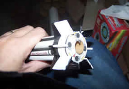
I carefully cut out the 4 LOX tanks and then cut out the 4 fuel tanks. I started on the pre-curling this time by taking out a table cloth while SHE WHO MUST BE OBEYED was asleep and folding it over until I had a very thick but soft working surface. Each of the tanks was then set upon it, one at a time, as I rolled the forming dowel over the top, pushing down progressively harder with each pass. This did get the process started, one of the hardest parts to me, but did not give the tanks nearly the curvature needed.
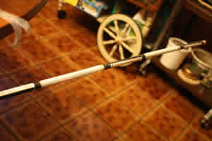
From there, I turned back to steam. I held each wrap over a pot of boiling water to give it some flexibility. Each wrap was the placed around a wooden dowel and held in place with monofilament line and tape. The dowel was significantly bigger than what was needed; I intended to do this in several steps. All of the wraps fit onto a single 4' dowel and were then exposed to the stream again and set aside to stiffen up.
The next day, the wraps were removed from the larger dowel. They had indeed acquired a healthy curve but the radius of the curve was still more than I wanted to deal with. I would have to repeat the process with a smaller dowel. The entire process was repeated, this time using a dowel only slight larger than the one that would ultimately be used to form them at the correct size.
When the wraps came off of the smaller dowel, they were much tighter. I crossed my fingers and hoped I would get it right this time.
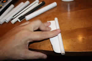
My amended tank rolling procedure began with placing a small piece of cellophane tape in the middle of the innermost part of the tank. I wanted just enough to adhere to the forming dowel for long enough to get the rolling started. The wrap was then rolled around the dowel and pulled tight. The process of pulling it tight gave me more "unrolled" material to wrap. A light skin of white glue was screeded across the backside of the tank wrap and the excess material was rolled around the dowel. While this was going on, I tried to carefully make sure that the tank was rolling straight. Before the glue could grab, I gripped the rolled tank in the left hand and used a pair of pliers to grip the forming dowel with the right. The dowel was then twisted to tighten the roll and the wrap was held in place like that until the glue gripped. When the glue on a tank had dried, I again gripped the tank with the left hand and the dowel with pliers with the right and then worried the tank back and forth as I pulled on the dowel. This sheared the tape and let me extract the dowel. It also produced a tightly wrapped tank. This slow process was repeated on the course of about 2 weeks until I had all 8 tanks.
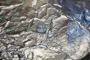
Cleaning out the garbage from the previous tanks had also been a long affair conducted over the months of the hiatus. Eventually, I got it to where the new tanks would fit and was happy that the innards would never be visually inspected too closely. One of the LOX tanks was chosen as the first victim and laid into place on some white glue that had been applied to the central tube and the remnants of the spider beams. That went well enough that I placed a fuel tank next to it. I then noticed that, although the tanks fit, they wanted to let their forward ends poke out past the forward bulkhead. Positive pressure was needed to keep them in place as they dried. I took a strip of aluminum foil and wrapped it around the tanks, pulling it tight to apply the desired amount of pressure and then taped it to itself to keep from marring the tanks. It was set aside to dry overnight. The next day I followed the same procedure adding 2 more tanks and wrapping them with foil to hold them in place. By this point, things were looking hopeful enough that I placed the remaining 4 tanks in one sitting and set it aside to dry. When I peeled back the foil. All the tanks were within bounds.
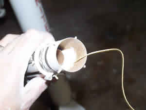
Astute readers and those with good memories will realize that even after all the months of construction on this beast, it still had no thrust ring. That is according to plan because the instructions at this point called for something I had not seen before. The thrust ring was to be mounted from the forward end. A long swab was used to put a ring of glue into place and then the back of the swab was used to force the thrust ring into place along the top of the engine hook.
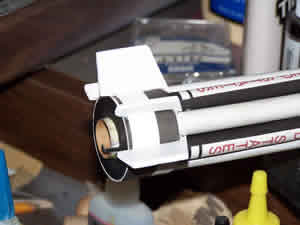
A centering ring, smaller in diameter than the ones previously used, was test fitted around the motor tube and found to fit just fine. It was glued into place near the top of the CR at the top of the tanks. It was also generously filleted since it would eventually be hidden. When that glue had a chance to stiffen up some, the shorter length of white body tube was fitted over the centering ring and glued flush with the ring right behind it. It too was given a generous fillet on the inside.
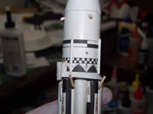
The large paper transition was located on the wrap sheet and cut out. A small amount of white glue was used to join the ring at the mark and it was then slipped over the upper body tube and settled into place to serve as a transition from the tops of the tanks to the smaller diameter BT.
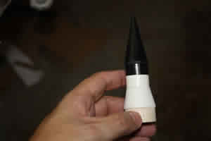
The nose cone had long since been painted white along with the short piece of body tube it fit within. The cone was glued into place in the tube. The bottom half of this tube was supposed to remain white but the upper half along with the cone needed to be painted black. With that in mind, the lower half was masked off to protect it from the black paint. The cone assembly was then taken to the spray booth and shot with a few coats of black. It remained there to dry.
Meanwhile, the body tube that had been glued to the coupler had a wrap to be applied. It was cut out and then carefully wrapped around the bottom portion of the tube. A light coating of white glue was used to make it adhere. The bottom of the body also had a wrap to be applied. It too was cut out and glued to the lowest of the BTs.
As I let the wraps set up, I went to check on the black paint on the nose cone assemble. I saw a few places that needed a little more paint and gave it a shot. The Wal Mart paint I was using dries fairly quickly to the touch so I was soon able to take it back to the bench and remove the masking. The freshly painted NC assembly was then glued to the balsa transition.
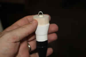
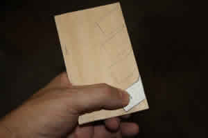
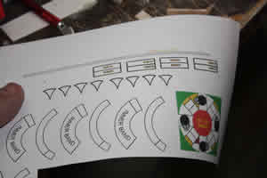
The rocket has two styles of fins, both of which need to be cut from the provided balsa. Templates are provided for both. The templates were cut out and then placed against the balsa and their outlines were traced with a pencil. Four of each were needed. A steel ruler was then used as a guide for the razor knife as all eight were cut out. Because I figured that painting the fins after installation would be a nightmare, I went ahead and filled them with Elmer's filler and set them aside to dry. At the same time, I installed the eyescrew in the base of the transition and secured it with some yellow glue.
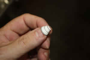
The engine nozzles on this kit are all built up out of paper wraps. Each one comes as two pieces called, logically enough, the inner and outer wraps. I cut the pieces for one of the nozzles out and curled them around the edge of a pair of scissors. The ends were then glued together. When the pieces were dry enough to hold together, the outer band was slipped over the inner band and glued in place at the bottom. The process was then repeated with the other 4 nozzles.
After having more than a few days to dry, I sanded the fins down and was pleased with their smoothness. They were then sprayed with Kilz and sanded again. The fins then received 2 coats of gloss white.
The wrap sheet came with 8 little pieces to be cut out and glued to the forward root edge of the fins and serve as fairings. They were cut out and glued to the fins with a dab of white glue.
When the fairings had dried, the process of applying the fins began. They alternate between large and small and are aligned with the grooves between the tanks. A double glue joint of white glue was used and 2 were done at each sitting. There was quite a bit of time between sittings but eventually all the fins and stub fins were in place. When in place, I used Tightbond Molding and Trim glue to run fillets on each of them.
Some Scotch tape was used to mask off the areas on the fins that were supposed to remain white and the some black acrylic was used to paint the black areas. As usual, I tried very hard to burnish the tape down well but there was still some leaking.
The paper nozzles that had been constructed looked fairly sickly at this point. I would have been greatly concerned if I had not gone through the same experience with the Zooch Discoverer Thor. I learned then that the hare-brained scheme to make them look better really does work, although they do look worse before they get better. Some strips of thread were cut to length as indicated in the instructions. CA was then used to tack the end of the thread to the nozzle at the junction between the upper and lower parts. I Started at the seam. The nozzles remained in that state for several weeks until I turned to them again. Then it was a process of slowly winding the thread around the upper portion of the nozzle and tacking it down with glue as I went. For some reason which escapes me now, I used white glue to do this. I tried to get the spacing as even as possible and only progressed very little each day. By the time the excess was trimmed at the top, they were looking really bad. The appearance started to improve dramatically when I brushed some acrylic aluminum paint onto the nozzles.
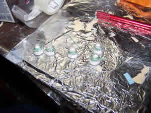
It was about the time that the last nozzle was painted that I realized that I had forgotten the turbo pumps. One of the provided dowels was cut to provide 4 pieces of the required, short length. The Zooch method for putting the pump on involves gumming up some glue, rolling it into a BB and applying it to the end of one of the rods. The gummy ball is then smoothed into the nozzle to create the "Illusion" of the pump. I tried doing this with Titebond Trim and Molding glue and quickly realized that that I did not have enough recreational pharmaceuticals to pull off the "illusion". I then tried to glue the rod onto the nozzles with the Titebond Trim and Molding glue directly. That worked, and since the stuff is thick and holds its shape, I was able to sculpt the "illusion" if you squint just right and your camera does not have a macro setting. Applying some more aluminum paint helped as well.
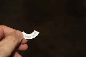
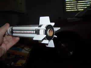
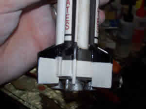
Most kits have little or nothing to show for their aft end. This one wants to make the aft end look good. Accordingly, the wrap sheet contains a disk to be cut out and applied to the rear centering ring. The piece was cut out and then the central circle was removed to fit around the motor mount. The piece was then applied the the rear centering ring with white glue and aligning the four nozzle bases with the four stub fins.
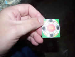
The graphic on the rear cutout helps to properly locate and place the four nozzles. The bases are indicated on the piece as are the connections to the turbo pumps. Little puddles of Titebond Trim and Molding glue were applied where the nozzles were to be located. The nozzles were then pressed into place and the a further dab of the Titebond was dropped down the bell of the nozzles and the pieces were set aside to dry.
When I returned to the project, I was still unhappy about the black paint that had seeped under the masking. A
brush and some white acrylic were used to make the situation slightly less egregious.

One of the joys and complexities of this kit is in all the little details tacked on under the general heading of "protrusions". There are a lot of them. I started with the ullage motors cut from the provided doweling. Four pieces were cut into 1/8" segments and then had an angle sanded into one end. The process of cutting cost me a few pieces which flew off never to be seen again and holding them while sanding with a pair of pliers cost me a few more. I figure I cut 8 to get four. They were placed with Titebond Time and Molding glue.
Next up came the retro rockets. These were provided precut and shaped and, unless I miss my guess, are formed from
the top ends of the higher end wooden toothpicks of the type that have a little groove cut around the top. I used the
Titebond to place these as well.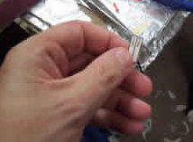
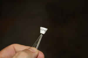
The rocket has 4 little antenna panels found on the wrap sheet. Their location is indicated on the instruction sheet but their orientation was not clear to me. I asked Dr. Zooch to clarify the situation for me and he did so promptly with the following message:
"I'll try and un-stuck you. First cut the FOUR antennas from the wrap sheet. Note their proper location on the S-1 stage. Run a bead of white glue along the long edge of the antenna. Stick it to the stage bridging the gap between the white tank and the black tank with the white tank on the LEFT and the black tank on the RIGHT. Allow to dry. DO NOT cut the antennas in half- if you have already cut tham in half, glue the halfs back onto a piece of paper- allow to dry and then cut the whole piece off again.
Good luck... we're all counting on you."
His message was enough to clarify things for me. I cut out the panels, folded them and glued them in place with Titebond Trim and Molding glue.
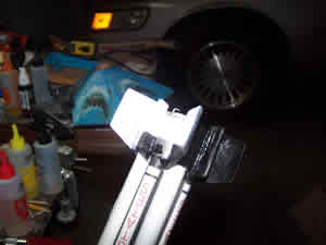
3 dowels had to be cut to a length of 4-3/8" to serve as piping between the tanks. Unfortunately, I read it as 3-3/8" the first time and cut the first one too short. These too were placed with Titebond. Three shorter pieces of dowel were cut to be applied as ducting a little higher up on the rocket.
The launch lug was to be cut into two pieces. The bottom piece was to be mounted in pretty standard fashion in the crook of a fin but the upper one needed a standoff to fit on the transition. A template provided for this purpose was cut out and the standout was cut from some scrap balsa. The leading edge of the standoff had a bevel sanded into it and then Titebond Trim and Molding glue was to fix the standoff to the lug. The upper and lower lugs were then glued into place using a length of rod to keep them aligned.
 My original intention with the shock mount was to attach a piece of Kevlar®
to the upper centering ring but I forgot. For that reason I went ahead and fixed a trifold but added a length of
Kevlar®
anyway.
My original intention with the shock mount was to attach a piece of Kevlar®
to the upper centering ring but I forgot. For that reason I went ahead and fixed a trifold but added a length of
Kevlar®
anyway.
The final step is the half year odyssey of this poor rocket being mistreated at my hands was to touch up some of the white paint on the various protrusions. I used white acrylic and a fine brush to apply paint to the scuffed parts, the glue and the unpainted retros. With that, I intended to fly it on the weekend.
Construction Rating: 4 out of 5
Flight:
My first outing with the SA5 ended without a flight because of lack of a chute. I normally substitute nylon chutes
for plastic ones. When I got to the launch field, I found that a 12" nylon would not fit and I did not have any
smaller ones on hand.
A week later, I decided to celebrate my birthday and Dr. Zooch's recovery from the swine flu by trying again. I installed a 9" nylon chute and then started thinking about a motor. Dr. Zooch is usually pretty vague on such matters except for explicit instructions not to "wimp out on an A." I decided to go with a B4-4 and set it up on the pad.
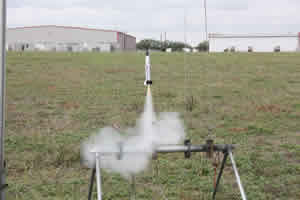
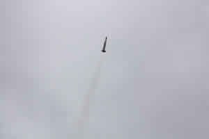
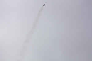
It took off well and flew straight to a pretty respectable altitude. When the thrust ended, though, it still continued to coast on momentum but slowed down quickly and began to fly a bit less straight. Ejection occurred perfectly at apogee while the rocket was horizontal. The chute deployed and it began its drift downward to land not too far away, although it had the bad sense to land on the opposite side of a barbed wire fence.
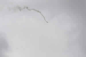
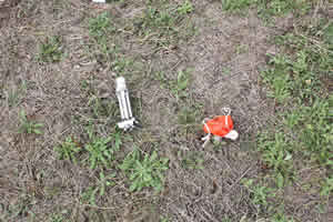
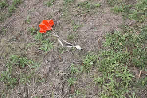
The rocket performed really well on a B4. For that reason, and because of my distaste for barbed wire fences, I felt pretty confident about trying the next flight on an A6-4. I loaded it up and took it to the pad accompanied by looks of incredulity from those who had heard my motor choice. The boost actually went pretty well. The rocket flew up and it flew straight. I didn't even really have any complaints about the altitude. It was the coast phase that really stank. The rocket decelerated quickly and started heading down. The problem was it kept going down. I have no reason to think the 4 second delay was inaccurate but if sure seemed like an A6-12 while at the same time the earth's acceleration field seemed to approximate that of Jupiter. As best I can tell, ejection occurred about 5 feet above the ground. This accomplished several things. It accelerated the nose cone giving it a deeper penetration of the ground, it broke up the aerodynamic shape so that the body did not hit quite as hard and, most importantly, it did get the bright orange chute out so that I could easily find the rocket when I stopped crying. Fortunately for me, the ground was very soft due to rain and there was no damage at all. I did, however, have to persuade the nose cone to let go of the mud.
Flight Rating: 4 out of 5
Summary:
This rocket took much more effort than I expected. Rolling the tanks, in particular, was a difficult task for me.
That said, I did learn a lot and I enjoyed putting it together.
It flew well also. It might even have done OK on an A8-3 but that's not something I'm planning on trying. It's a good product and the service and support from Dr. Zooch are excellent.
Overall Rating: 4 out of 5
Other:
Persons interested in following this rocket can find its service life documented here:
http://www.flickr.com/photos/23694991@N03/collections/72157617582604204/
Other Reviews
- Dr. Zooch Saturn I Block II SA-5 By Chan Stevens
This is another fine ant-scale offering by Dr. Zooch. I believe this is the only commercially available model of the SA-5 version of the Saturn 1. It is an excellent value and a great flyer. Scale modelers will be impressed by the level of detail. Please see Jeff Ridder's Saturn 1 Block II (SA-6-SA-10) and my Saturn 1B review for more details on the parts list and construction notes. This ...
 |
 |
Flights
|
|
Sponsored Ads


|
|
K.G. (January 2, 2007)