Scratch Cobra II Original Design / Scratch Built
Scratch - Cobra II {Scratch}
Contributed by Tom Benson
| Manufacturer: | Scratch |

Brief:
The Cobra 11 is an 11th hour entry into the EMRR Box 'o Parts contest. Special thanks to Todd Mullin (punkrocketscience on The Rocketry Forum) for all the work he did sorting and reshipping the materials!
Tubes and more tubes! The box-o-parts came with so many tubes that I immediately thought of tube fins and clustered motor mounts. Then I thought about putting those cluster mounts _IN_ the tube fins. And I did have a lot of those plugged A10 mini-motors. So an idea was hatched for a 3 motor cluster rocket with 3 outboard pods. Clusters are cool and besides, they score bonus points in this contest. So looking at the parts available to me, I opted to make an "old school" Estes Cobra-type rocket.
Construction:
Parts List:
- BT50 nose cone
- BT50 clear payload tube, 4"
- BT50 body tube, 5.25"
- BT50 motor tubes, (3)
- BT50-60 balsa transition
- BT60 body tube, 13.5"
- BT5, 9"
- 18mm motor blocks, (2)
- 3/16" Balsa fin stock, 3"x 10.5"
- 1/8" Balsa fin stock, scrap, roughly 3"x 7"
- 18mm yellow spacer tube
- 24mm yellow spacer tube
- 14" Quest plastic chutes (2), and thread
- Screw eye
- 1/8" Elastic, 6'
- Bamboo skewers, (2)
- Avery label paper, (1/2 sheet)
- 1/8" Launch lugs, (2)
- 20lb paper, about 5 sheets. Printed on one side, creased and folded and stapled.
Build the motor mount. Three pre-cut motor tubes came on the box, how nice! Only two engine blocks included though. Three 3/8 inch sections are cut off a yellow spacer tube. (The kind usually discarded after being used to push an engine block into place.) One ring is then cut vertically, placed inside the motor tube, and the overlap is noted. This strip is trimmed out. The ring is test fit and then glued in place. The third section is then prepared the same way and fit into the second. Glue the other two motor blocks into the other two motor tubes, then glue the tubes together.
Fin design. Balsa was in short supply so a major goal in picking a fin layout and shape is to maximize the stabilizing effects of the available material. Six fins will be made from the materials available. I cut 3 fins from fat 3/8" balsa, using as much of the sheet as possible. Then 3 smaller ones were cut from thin 1/8" material; these would be attached to the outboard motor pods.
Fin alignment. The two fin designs will be alternately placed around the rocket. I used an Estes fin alignment guide, which has detents at 0, 90, 120, 180, 240, and 270 degrees. I fit the main BT onto it and marked with a pencil at 0, 120, and 240. Then I rotated the BT so that my first mark was aligned with the 180 detent. I made marks again at 0, 120, and 240, giving me a total of 6 lines evenly spaced around the outside of the tube. I lengthened these lines by placing a strip of angle iron against the tube as a guide.
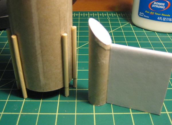
Side pods. I cut BT5 tubing on a 45* angle using a razor saw and mini miter box. I drew a circle of glue on scrap paper and dipped the BT5's beveled end into it. Then I cut a 1" square of balsa and pressed the BT5 onto it. When the glue was dry I trimmed off the excess balsa and then sanded the edges flush to the tube. This was repeated for the other two pods.

Papering the fins and pods. Those old printouts would be used to paper the fins. The trick was to have the unprinted side face outward and avoid using creased areas. I used 3M 77 spray to stick the paper to the balsa, then trimmed off the excess paper. Worked great as always to strengthen the balsa and provide a smooth surface. However it was not an ideal technique for the side pod "caps". Trimming off the paper proved to be difficult because of the bevel. It also does nothing to cover the exposed edge of the balsa. (Wood Filler would have been a better way to smooth out the pod tops.)
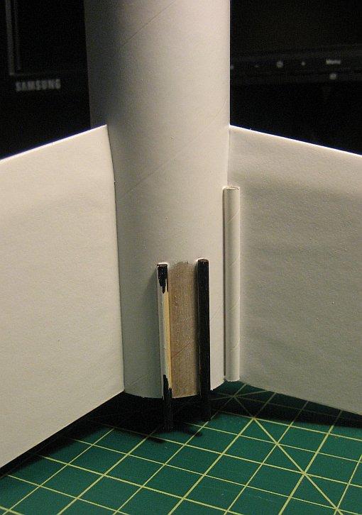
Small fin attachment. The small fins were glued to the short side of the pods. I wanted to paint the pod assembly separately but I also didn't want to glue onto a painted surface. These short, small diameter tubes would present very little surface area for glue against the main BT60 body tube. Pretty weak considering they'll be packing A10 motors. I decided to beef up the attachment area. Bamboo skewers were cut into six 2-inch dowels. These were tacked in place with CA about 1/8" on each side of the BT markings for the pods. If done right the pods would rest against both dowels and the body tube. Mine weren't perfect but close enough that a few thick glue fillets would close the gaps.
Large fin attachment. The 3/16" balsa is so thick that it doesn't rest well against the curved surface of the body tube. So I sanded a very shallow channel down the centerline of the fin's root edge. The fins were then attached to the body tube with double wood-glue joints. Two thin white glue fillets were added later.
Launch lug. One into a fin fillet, another further up the body.
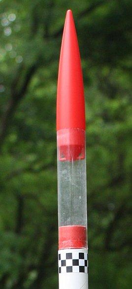
Spacer tube saves the day. A lowly 24mm yellow spacer tube provided materials for both an adapter and a coupler block. One end was dipped in glue and then pressed to a small square of balsa. When dry, the excess balsa was trimmed away and sanded flush to the tube's edge. This assembly was a loose fit inside BT50 so some Avery label paper, printed red to match the nose cone color, was wrapped around the spacer tube. Another piece was used to cover the balsa cap. The spacer tube was then cut in half.
Payload. The piece of spacer that had a cap was glued halfway into the top of the upper body tube. The payload section was then attached with Testor's glue. The red color visible through the clear tubing balances the red nose cone shoulder.
Transition. The transition's top was too skinny for BT50, so I glued the other half of the 24mm spacer tube onto it. The transition's base was too thick, so I used a file to bring it down to BT60 size. An eye hook was screwed in, then backed out again. A drop of wood glue went into the hole and then the hook was replaced.
Finishing:
The balsa transition was rough and needed to be filled. I spread undiluted Fill+Finish wood filler around, avoiding the shoulders, and then "dry rubbed" it into the grain with my fingers. Rub vigorously and the excess F+F comes off, leaving a smooth surface. Almost No sanding! The fins were paper covered and the outside + trailing edges filled with a FnF dry rub. NO Sanding!! And the spirals on all the body tubes were tiny so I opted not to fill them. NO SANDING!!! Sweet. In keeping with the No Sanding theme, I skipped the use of primer and went straight for the paint. Besides I was running out of time before the contest deadline.
My paint masking skills are weak, so from the beginning I had planned the build process to avoid this. Parts would be built into modules, then the modules painted before final assembly. I only needed to mask the small areas where the pods met the main body tube, between the bamboo dowels.
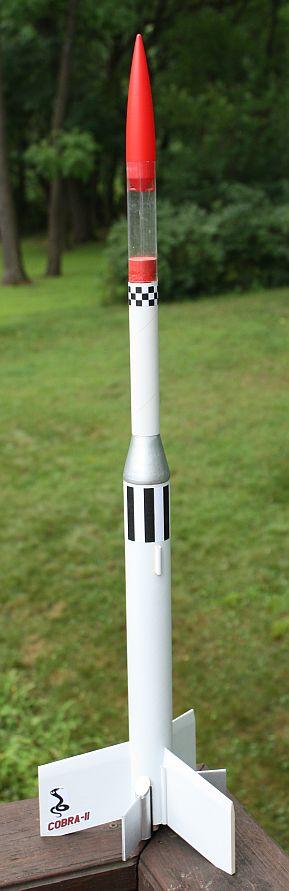
The body got several light coats of Krylon Semi-gloss White. The transition and external motor pods were painted Krylon Silver. The silver-colored pods blended right into the white of the body - to make them stand out more I used a black Sharpie marker to color the bamboo rods. The nose cone was already a nice color red - after extra flashing was carefully removed I simply coated it with NuFinish.
Decals. I created some classic roll-patterns and other decals in Inkscape. These were printed printed on the supplied half-sheet of Avery label paper. The sheet was sprayed with two light coats of fixative before the decals were cut out and applied.
The completed rocket had a nice semi-gloss finish overall. I liked it so I did not try to apply any clear coat.
Final assembly. The transition and payload area were then glued together. The shock cord was attached with a traditional tri-fold mount. The motor mount was glued in, but what to do about the gaps? I tore a few chunks of cardboard off the shipping box and soaked them in water overnight. The layers softened and separated. The cardboard was squeezed dry, coated with a little Gorilla glue, and wadded into the motor mount gaps.

Flight:
The rocket was completed on the day before the contest deadline! And the forecast for the next day was rain! Why did I wait so long? I charged my launch battery that night, in case the weatherman was wrong. Oh yeah, and I had to solder together a clip whip too! The next morning there was drizzle and a heavy low cloud cover, but just after lunch the clouds lifted a little and the sprinkles subsided. So it was a race to the park!
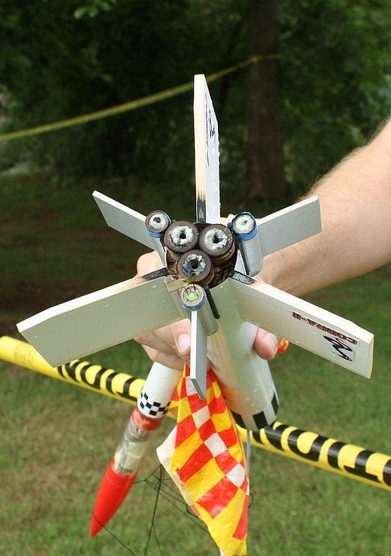
I might only get one flight in before the rain came back, so why not go for broke? The central 18mm tubes were loaded with C6-7s and the outer 13mm tubes got A10-PT's. Motor retention relied on fiction fitting with masking tape. There are no motor blocks in the pods so a few extra wraps of narrow tape were wrapped around the nozzle end to prevent the A10s from shooting through the tops of the pods. It felt tail heavy so I put a 1 ounce bag of sand into the payload section to move the CG up. Man, it took a long time to prep and hook up 6 motors.
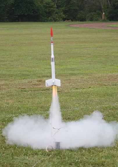
On ignition there was plenty of smoke and fire. The flight was magnificent! Straight and true, she flew to maybe 1000 or 1200 feet. Ejection appeared to be right at apogee (though to be honest it was hard to see.)
Recovery:
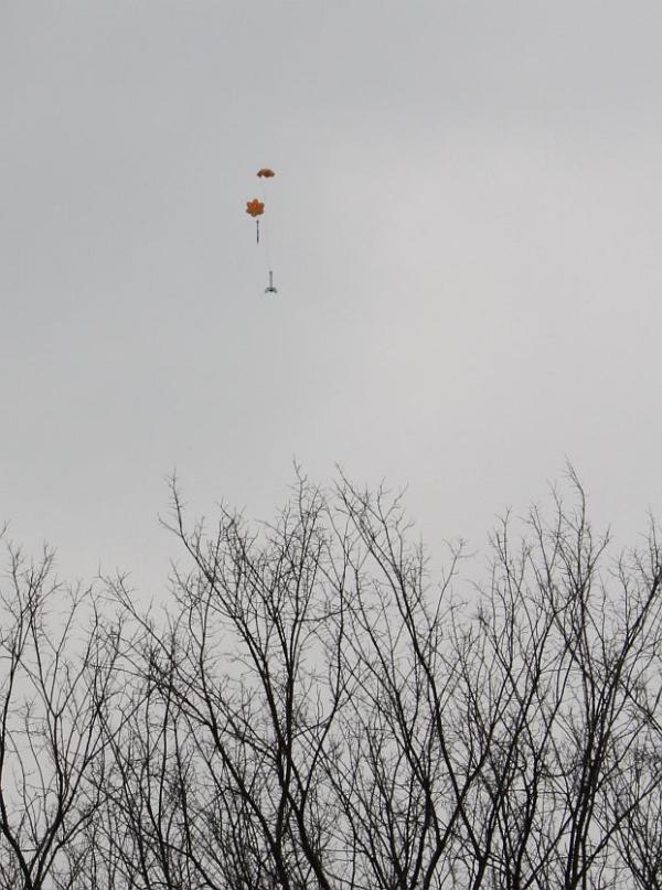
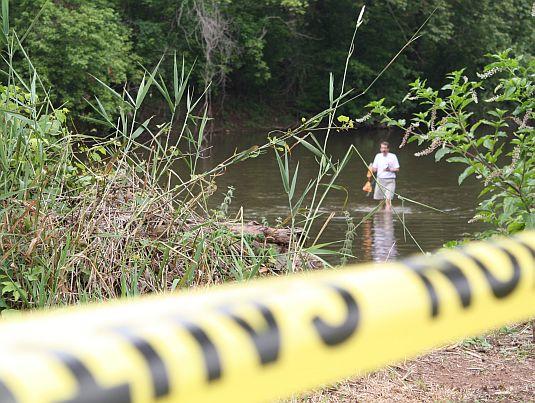
Both chutes deployed perfectly. One had been attached to the middle of the shock cord and the other to the transition's eye hook. The rocket descended at a good rate, but a breeze blew it toward the edge of the park. The good news was it missed the treeline. The bad news was it went into the river. Splashdown!
Five of the six motors had lit. One of the outboard A10's still had a plug and igniter in it.
Four motors had swollen with water so badly that I couldn't get them out. Her impressive maiden flight may be her last. I need to let the rocket dry out a bit and see how it goes.
Summary:
That was my first big cluster rocket and I'm very happy with how it flew. I think I received the right mix of Parts to Junk in order to keep the competition fun, challenging, and not too serious. It was a good way to find new uses for odd parts, and try new techniques, both for building and flying.
I now have some unusual parts left over that can be used to scratch build other things. Or they can go back into the pool for next year's contest!!!
Sponsored Ads

 - Ancient Prophecy - 1st Edition - Rare")


 | Intermediate Rocket Kit | Step-by-Step Instructions | Science Education Kits | Great for Teachers, Youth Group Leaders and Birthdays,Blue")

, Launch Pad/ Controller, Glue, Four AA Batteries, and Two Engines")


 |
 |