Scratch G.B.R. (gold, black, red) Original Design / Scratch Built
Scratch - G.B.R. (gold, black, red) {Scratch}
Contributed by Robert Davis
| Manufacturer: | Scratch |
 Here is my rocket design
submission. Thank you.
Here is my rocket design
submission. Thank you.
This rocket has a 24mm motor mount and weighs in around 2.75 ounces (empty), so she's a high flier on D12 motors. It can also be flown on C6 motors. I employed TTW fin attachment, so I'm sure it would do great on E15 or E30 SU motors. That is why I built the motor mount for "E" motors instead of "D".
Construction:
To make this rocket you need:
Parts List:
- 1 Estes 18" BT 55 tube
- 1 PNC 55 nosecone (5.5" long, conical or ogive, depending on preferences)
- 1 24mm motor mount for an Estes "E" motor (or 4" of BT-50)
- 2 AR5055 BT 55 centering rings (Estes #30166-2)
- 1 "E" Engine hook (Estes #35022)
- 1 engine block (can use a 1/4" wide section of a used "D" motor)
- 3/16" x 2" launch lug
- 12" parachute (I used Estes plastic, but nylon might be preferred)
- 3/8" elastic shockcord (I used 50" worth)
- 1/8" x 3" x 18" balsa stock for the fins
- 1 square of Estes clay for nose weight (not sure on the weight)
I used 15 minute epoxy for all construction to ensure the rocket's fins would withstand "D" and "E" motor flights.
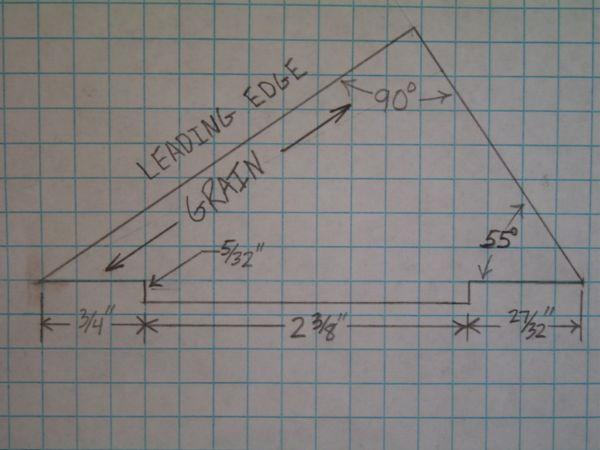
The first step is to cut the fins. The fins attach to the motor mount through the wall of the body tube to provide for more strength. Making the fins from the template is easy, as long as the template is correct.
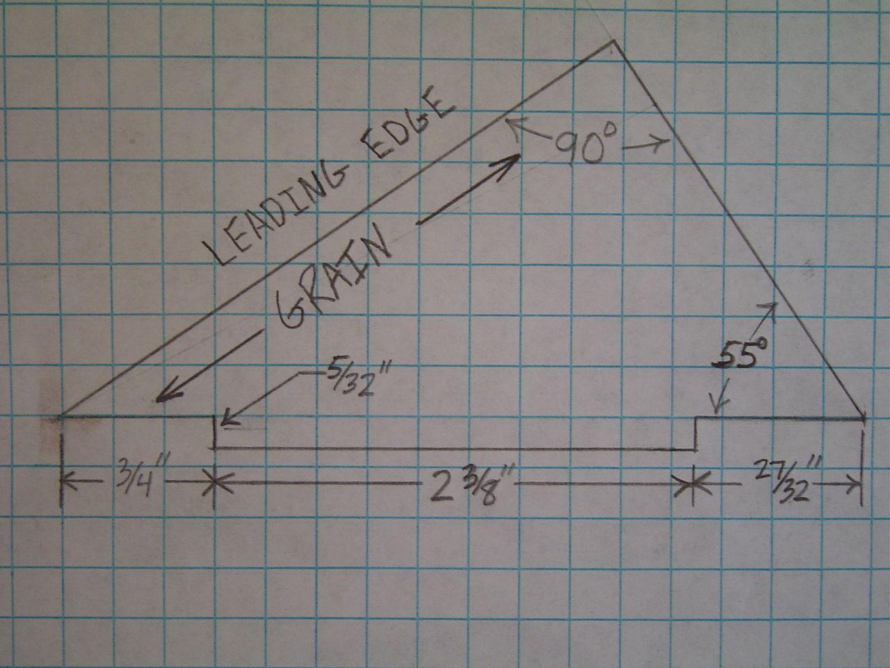
I placed the template against the two square sides of the balsa stock so I would only need to cut one side, then I used the first fin as the template for the rest of them. Sand fins so that they are the same size, then sand leading and trailing edges for desired shape, if desired--I went with airfoil shape.
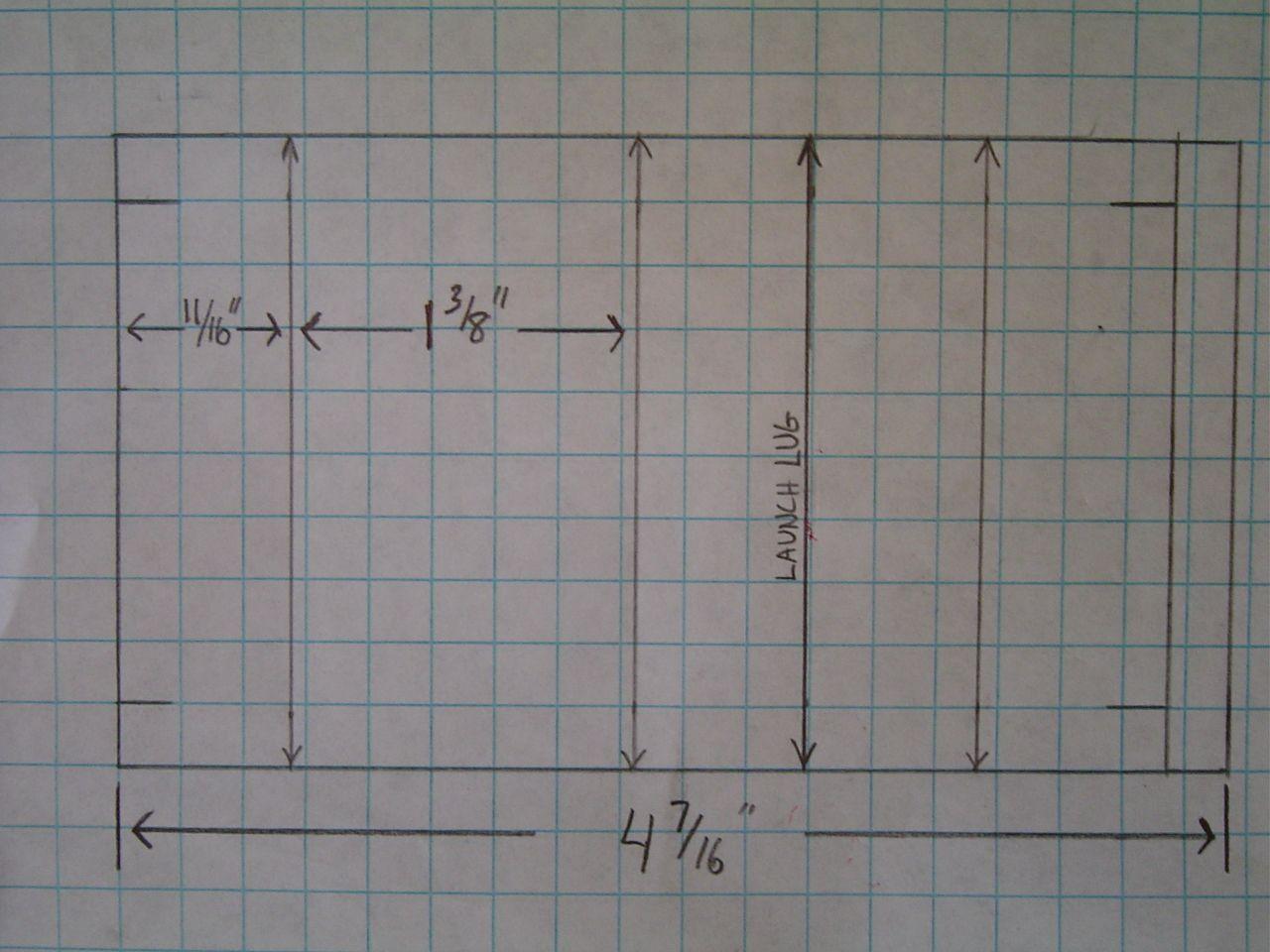
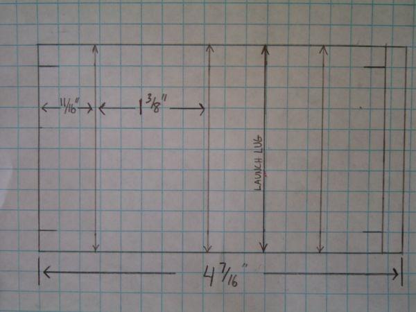
Now you need to mark the body tube for the 3 fins. I made a fin marking guide similar to an Estes one, and that wasn't very difficult. After marking the lines for the fins and the launch lug, extend them all a good five inches or so, and take the LL line up about 8 inches. Mark along the LL line a spot 11-13/16" from the front of the body tube. This is where the LL will go. On each fin line, place a mark 5/8" from the rear of the tube, and another 3" from the rear. Using a sharp hobby knife, cut alongside the fin lines (offset 1.5mm each side) between the two marks you made, This is for fin attachment. Once the cuts are done, test each fin into the slots. Sand as needed. They should extend approximately 1/4" behind the rear of the body tube.
Assemble motor mount and centering rings as per instructions provided in the Estes "E" motor mount kit. If you are without a kit, the assembly is easy.
You may want to mark the motor tube on one end as "front" as to not get confused
Make a 3mm long cut, across the tube, 1" from the front of the motor tube
Mark a line, across the tube, 5/8" from the rear of the tube
Insert "E" hook into the cut you made, extending to the rear of the tube
Fit one centering ring up to the 5/8" mark, and the other up to the 1" spot where the hook is inserted. -- You may want to dry-fit the rings to ensure proper fit. There should be approximately a 2-3/8" gap between the front and rear rings. Be sure it is big enough since the fins will attach there. Glue into place with epoxy
Slide engine block into front of motor tube so that it stops against the section of hook coming through the top and glue it in place
 Once the epoxy has cured enough,
the motor mount is installed flush with the end of the body tube (the engine
hook will stick out quite a bit). Be sure the centering rings are not inside
the slots in the tube, as this will prevent your fins from fitting in the
slots. Be careful not to get epoxy into the fins slots. Let dry.
Once the epoxy has cured enough,
the motor mount is installed flush with the end of the body tube (the engine
hook will stick out quite a bit). Be sure the centering rings are not inside
the slots in the tube, as this will prevent your fins from fitting in the
slots. Be careful not to get epoxy into the fins slots. Let dry.
Test the fins into the slots one more time and do any sanding as needed. Once you are sure they all fit perfectly, put generous amounts of epoxy on the root edge of a fin and glue into place. Ensure it is in there straight. Let dry. Repeat with the other two fins, one at a time. Once the fins are all dry, apply fillets and let dry.
After the fins have been attached, take the launch lug and glue it onto the LL line so that the front of the LL rest on the 11-13/16" mark you made. Make sure the LL is straight and let dry, then apply fillets.
Shockcord attachment is a matter of preference. I chose the Estes method on this rocket, making the shock cord mount from some scratch paper. I used 50" of 1/8" elastic shock cord and attached it two inches down inside the body tube using generous amounts of epoxy.
Pack the clay square into the nose cone. It helps to roll the clay into a long snake, and then put that through the hole in the rear of the nose cone. I'm not sure what the weight of the clay was, but it is probably around 1/2 oz. Attach the nose cone to the shock cord, then attach the parachute to the shock cord about 3" or so from the nose cone.
Finishing:
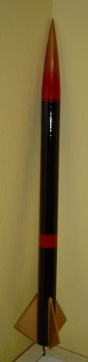
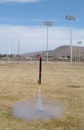
The rocket was lightly sanded to aid in paint adhesion, then two layers of gray primer were used, lightly sanding between each application. I chose black for the body tube, gold for the fins, and a gold/red fade on the nose cone. I also added a couple of red strips around the body tube, with one of them at the top. Two layers of paint were used on all parts, then finished with Krylon Clear Glaze for a nice, glossy appearance.
Flight Tests/Motor Recommendations:
 Rocksim showed that
"D" - "F" motors would be fine for the rocket. Predicted
altitudes for a D12-7 were between 1200' - 1400'. Aerotech E15-7 motors should
reach about 2700', and the E30-10 a little lower at about 2600' (but hitting
575 mph). An "F" will take it past mach, and also send it flying very
high, as long as the balsa holds up.
Rocksim showed that
"D" - "F" motors would be fine for the rocket. Predicted
altitudes for a D12-7 were between 1200' - 1400'. Aerotech E15-7 motors should
reach about 2700', and the E30-10 a little lower at about 2600' (but hitting
575 mph). An "F" will take it past mach, and also send it flying very
high, as long as the balsa holds up.
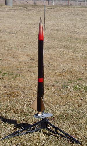
The first flight was on a single D12-7 in a 2-5 mph wind. Since the motor mount is for an "E" motor, I used an Estes EC-75 "D" engine spacer to take up the empty space inside tube. Lift-off was fast, and flight was arrow straight. I had no way of checking the altitude, but it easily went over 1000' and took quite a while to make it's way back down, even under the small 12" parachute. Ejection was at apogee--perfect. It was a perfect launch.
Second flight was to check for the rocket's ability to fly under "C" power. I used an expended "D" motor and bored the nozzle end out a little to allow ejection gases to freely pass through. I then friction fit a C6-3 inside the "D" casing so that the nozzle end protruded out the rear, then placed tape around the two cases to ensure the "C" motor would not kick out on ejection. Flight on the "C" was great. Nice lift-off and perfectly straight flight, reaching about 500' - 700'. Ejection at apogee again. Rocket came down nicely about 75' away.
Third flight: AT SU E30-7 Fast lift-off and arrow-straight flight to around 2300'. Ejection was at apogee. Parachute didn't unroll due to stuck shroud line, but rocket recovered safely with only a small crack in one fin. Repairable and will fly again.
Summary:
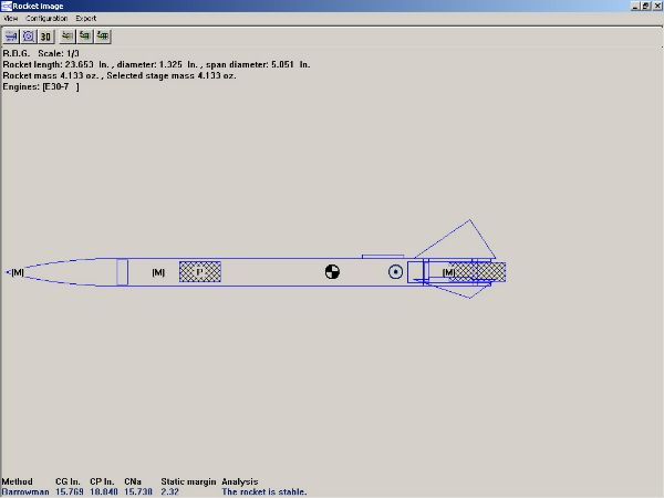
Both launches prove what Rocksim showed--the rocket is very stable and a good flyer. I'm sure it will perform well on any "E" motors you give it. It may even fly on a "B" with a short delay, but that was not checked on the simulator. Rocksim showed a CP (Barrowman) at 18.840, and a CG of 15.585 when loaded with a D12 (I checked the CG just before flight and showed 16.45)--either is stable. Weight loaded with D12 is 4 oz.
Pros - TTW fin mounting. Flexible in the range of motors it can use, which eases stress on the pocketbook and allows for various conditions. Flies high due to weight.
Cons - Need to be very careful when cutting the slots for the fins to avoid misalignment.
Sponsored Ads

, Launch Pad/ Controller, Glue, Four AA Batteries, and Two Engines")


 |
 |