Descon Generation Ship Calypso
Scratch - Generation Ship Calypso {Scratch}
Contributed by Stuart Lenz
| Manufacturer: | Scratch |
Generation Ship Calypso
by Stuart Lenz
 During the early part of the 21st
century, the first extra Sol planets were discovered. First discovered were gas
giants larger than Jupiter in close in orbits of their stars. Shortly there
after, even Earth size planets were being found. This was fortuitous for the
human race, because at the some time the planet earth reacted violently to the
pollution and global warming that had been going on since the beginning of the
Industrial Revolution. Global ocean currents stopped flowing and then the quick
onset of a massive Ice age with the habitable areas reduced to less that 10
percent of the previous land areas. This was the impotence for the development
of the first Generation Ships, ships designed to carry the human race from a
now icy Earth to new homes around other stars.
During the early part of the 21st
century, the first extra Sol planets were discovered. First discovered were gas
giants larger than Jupiter in close in orbits of their stars. Shortly there
after, even Earth size planets were being found. This was fortuitous for the
human race, because at the some time the planet earth reacted violently to the
pollution and global warming that had been going on since the beginning of the
Industrial Revolution. Global ocean currents stopped flowing and then the quick
onset of a massive Ice age with the habitable areas reduced to less that 10
percent of the previous land areas. This was the impotence for the development
of the first Generation Ships, ships designed to carry the human race from a
now icy Earth to new homes around other stars.
Constructed in orbit…
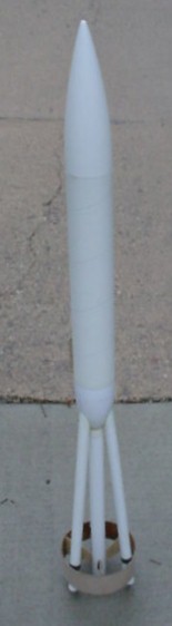
Parts
- Ogive Nose Cone Bt 80 from Estes V2/Phoenix
- Oval Nose Cone Bt 80 from Estes Fat Boy
- Body Tube Bt 80 (14")
- Body/Motor Tube Bt 50 (22")
- Body/Motor Tubes 3 * Bt 20 (17")
- Motor Clips 3 for 18mm Motors
- Paper Rings 3 to hold Motor Clips
- Ring Fin 2" of LOC 5.5" Body Tube
- Plywood for bracing 1/16" 3 ply Plywood
- Centering Rings 2 * Bt 55/50
- Thrust Ring Bt 50/20
- Thrust Rings 3* Bt 20/5
- Kevlar String As Required
- ¼" elastic shook cord As Desired
- Launch Lug 2 * 3/16 (2")
- Parachute As Desired (24" Estes used)
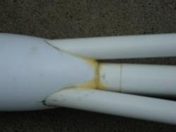
Our construction starts with laying out of the tail cone (Fat Boy Nose Cone) . This requires a central core Bt 50 tube centered through the tail cone and three holes for the three coaxial Bt 20 tubes evenly spaced around the central Bt 50. The three Bt 20 tubes will extend ~16" rearward and attach to the Ring Fin. The Bt 50 tube was then glued into the tail cone using the two Bt 55/50 centering rings with ½ " extending through the tail cone and the remaining 16" protruding out the rear. Once this is dry, the Bt50/20 thrust ring is inserted and glued into the Bt 50 tube using a spent 24mm E motor to set the correct distance (with ¼" of the motor protruding).
The three Bt 20 tubes each have a Bt20/5 thrust ring inserted and glued in, using a spent 18mm motor to set the correct distance (also with ¼" of the motor protruding). These tubes are then marked and glued into the tail cone and to the central Bt 50 Tube. They were braced into their final positions and allowed to dry. The ring fin can be used to help hold them in position until dry.
 For the Ring Fin, I used a 2" piece of
LOC 5.5" tube form the parts box, but such a ring can also be created by
rolling one from paper or balsa around a form of the correct size. I applied CA
to both edges of the ring fin and then trisected it into equal parts. (This was
done by wrapping a piece of paper around the outside of the ring and making a
mark where they overlap. Then unwrapping the paper and using a ruler to divide
the marked distance into 3 equal distances. This was then transferred back onto
the outside of the ring fin.) A spent 18mm motor case is then wrapped with
sandpaper and used to sand groves in the inside bottom edge of the ring fin
where the Bt 20 tubes will be attached. These tubes extend ½" past
the bottom of the ring fin.
For the Ring Fin, I used a 2" piece of
LOC 5.5" tube form the parts box, but such a ring can also be created by
rolling one from paper or balsa around a form of the correct size. I applied CA
to both edges of the ring fin and then trisected it into equal parts. (This was
done by wrapping a piece of paper around the outside of the ring and making a
mark where they overlap. Then unwrapping the paper and using a ruler to divide
the marked distance into 3 equal distances. This was then transferred back onto
the outside of the ring fin.) A spent 18mm motor case is then wrapped with
sandpaper and used to sand groves in the inside bottom edge of the ring fin
where the Bt 20 tubes will be attached. These tubes extend ½" past
the bottom of the ring fin.
One launch lug was attached to the bottom of the Bt 80 just above the tail cone and the other one on the lower brace in line with the upper launch lug.
The rocket was flown on November 13th, 2004 at the Tripoli Minnesota high power launch. On the first attempt, only a single F21-6 motor was used in the center position.
A second flight was not possible due to our seasons and available launch sites but was planned to be 3*C6-5s, followed by a full up flight.
Sponsored Ads


![Vintage Estes Viper #0820 Model Rocket [4*G-17.25]](https://i.ebayimg.com/thumbs/images/g/Q7EAAOSwN1Nl1kDF/s-l225.jpg "Vintage Estes Viper #0820 Model Rocket [4*G-17.25]")


 |
 |