Scratch MMX Club Launch Rack Original Design / Scratch Built
Scratch - MMX Club Launch Rack {Scratch}
Contributed by John Lee
| Published: | 2010-02-23 |
| Manufacturer: | Scratch |
Brief:
In checking my club's flight cards for the last 2.5 years, I find that there have been 8 MMX
launches. All of them were done by me. I have tried to see if there was any interest in an informal MMX contest of some
type on several occasions and there was not. In delving a bit deeper, I learned that MMX was not disdained because of
its diminutive size, it was shunned because of the hassle, real and perceived, of flying them. That was an attitude I
shared myself. Every time I thought about building or flying one, I usually gave it up as too much hassle.
That is especially true of the ground support equipment. The silo launchers are problematic and I have had only one good launch off of one. The rest of the time I have had to kludge something together, cross my fingers and hope it works. It sometimes even does.
This is not to say that there are not some great MMX GSE ideas out there. There are. They just don't strike me as worth the effort. I finally decided to see if I could design something to take some of the hassle out of it and make it fun. In effect, with a minimum of effort, I want to be able to treat an MMX rocket like any other. Go out to the assigned pad, hook it up, walk away and have reasonable confidence that the rocket would launch. I wanted to be able to do this without lengthy preparation of special consumables. In order to do it, I was willing to invest some time, effort and money into making such a system.
The basics that I wanted to accomplish are these:
- Build the project with readily availible parts; no machining or milling.
- Be able to use any of the common igniter options without having to switch gear.
- Be dependable; the same ration of successful launches as will the bigger gear.
- No hassle, perceived or real.
Construction:
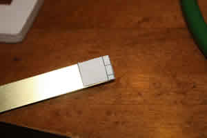
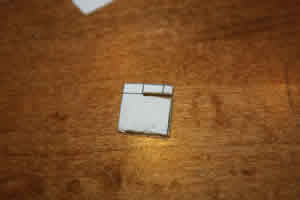
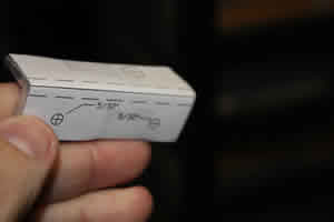
The first step in this grand project was to get out an MMX igniter, measure it and make a drawing of it
 in Autocad. I measured to 1/16" and estimated to 1/32" I think it will be good enough for my purposes. I
wanted the DWG files of the various igniters I want to plan for to use as blocks in the drawing files help me draw up
the ignition system. I also wanted to have a half decent chance of having the thing work when I got through. I also
cracked open the plastic case and made a drawing of the naked igniter. With that done, I could start drawing up the
head.
in Autocad. I measured to 1/16" and estimated to 1/32" I think it will be good enough for my purposes. I
wanted the DWG files of the various igniters I want to plan for to use as blocks in the drawing files help me draw up
the ignition system. I also wanted to have a half decent chance of having the thing work when I got through. I also
cracked open the plastic case and made a drawing of the naked igniter. With that done, I could start drawing up the
head.
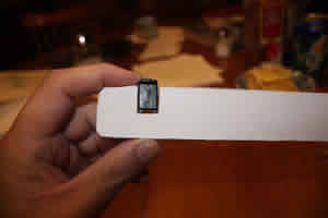
I had liked what I had seen of several ideas that used a slot to support the igniter and that was a part of the idea as well. That being the case, the first thing was to come up with the arm that provided the support. I decided on 1/4" plywood as the basis for the framework. I picked it for dimensional stability and because it is an insulator. Most important, though, it has laminations oriented at different angles so that shear should not become an issue. This was because I planned on a relatively skinny support, for reasons which will later become apparent.
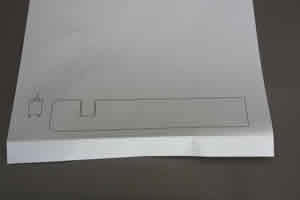
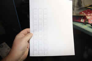
I opened up Autocad and drew up a support arm that had a slot that was just a touch bigger than the plastic encased igniter. At this point I did not concern myself with length, only the part that would support the igniter. I then printed out this simple drawing.
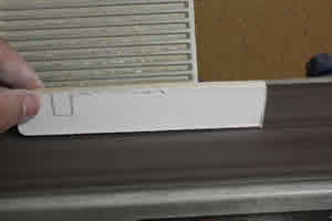
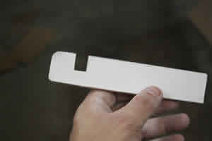
Although the support beam would ultimately be of plywood, I did not use plywood at this stage. I chose instead a scrap of 1/4" balsa since it would be easy to whittle on and adjust and because it happened to be handy. The template was trimmed a bit and then applied to the balsa with a glue stick. The rough piece was then taken to the belt sander and the profile was trimmed down to the outer edges of the template. With the outer edges taking place, a razor knife was used to carve out the igniter slot.
Later that night, it was time to examine the first fruits of the project and I spread my stuff out on the kitchen table after the Mrs. had gone to bed. I put in the plastic igniter ans was glad to see it fit; with me doing the measuring and cutting, such things cannot be assumed. I also test fitted the stripped down, paper clad igniter and it fit as well.
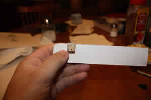
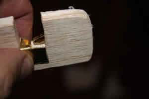
One of the problems I had experienced with other MMX systems was the attachment of the microclips. My scheme was to get rid of the "micro" altogether and replace it with "macro". I found a plastic clamp at Lowes that seemed to fit the ticket and tried it on to support the plastic igniter. At first blush it seemed to work. Looking at it from the top, though, there was a slight problem. The grips on the clamp were just a touch wider than the slot. For the ultimate plan, they needed to fit flat within the slot.
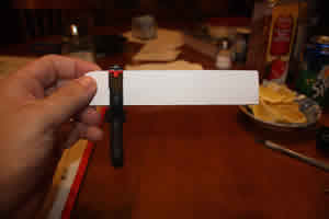
Before doing any adjustment, though, I wanted to try it with the naked igniter. I slipped it into place, oriented 90 degrees from the way the plastic one had been, and made sure the leads extended on either side of the support. The clamp was then placed, much lower down this time, pinning the leads to either side of the support arm. I then spent some time fussing with it. Key to making my scheme work was the degree of stiffness of the igniter in this orientation. It seemed to me that the clamp was sufficiently tight to hold it in place without any wiggling.
With the information I had gotten thus far, I went back to Autocad and widened the slot by 1/32" on each side.
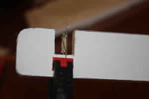
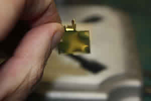
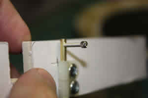
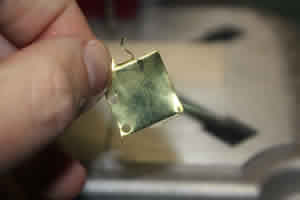
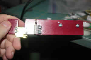
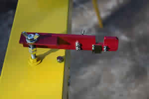
To provide electrical contact, I intended to use a pair of brass pieces, one on each side of the launch head. each would be primarily vertically oriented so that a naked or standard ingniter could be set in place with one lead clamped to either side. I also intended to fold a small piece of brass over the top to catch the leads on the classic MMX igniter.
I went into Autocad and drew up a plan for the brass pieces assuming that I would be using 1/2" wide brass. The lines for folding and cutting were marked interchangeably. A copy was then printed, cut out and taped to a piece of 1/2"x0.016"x12" piece of brass. A cutoff disk on a Dremell tool was then used to cut the piece to length and slice the part that would be folded back. A pair of pliers was then used to make the bends and folds. The folds were not completely bent into shape under the theory that some finagling would be needed and I wanted to fatigue the metal as little as possible. An identical piece was then cut and formed and the pair was test fitted into the head.

Soldering is not one of my strong skills, and that's putting it kindly. Even so, I felt obligated to provide the electrons with a path to get to the brass contacts. I took a length of speaker wire, stripped the ends and then soldered a lead to the back of each of the contact plates.
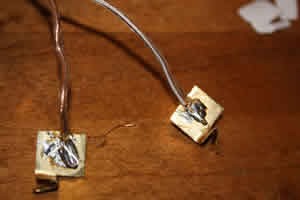
In order to accommodate the solder on the backs of the contact plates and allow them to lie flat, I had to excavate a cavity on either side of the head. It was done by trial and error with an ambiguous head on the Dremmel.
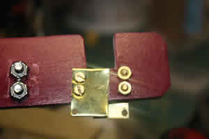
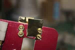
Since this was merely a proof of concept prototype, I did not take the trouble to fasten the plates to the head in a "good" manner. Instead, I just epoxied them into place and clamped them to set. This proved to be a mistake since some of the epoxy developed and unhealthy relationship with the clamp and the removal of said clamp distorted things.
Several tests were made with the prototype and I found that the concept did work but that there were some problems with execution. Aside from the not so durable balsa used as the head, the method of attaching the wires to the plates and the plates to the head were also problematical. As I considered how to deal with these issues, I turned my attention to the "guts" of the project.
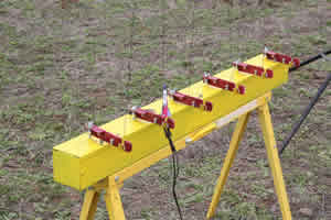
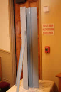
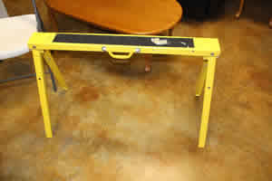
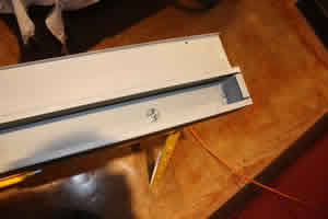
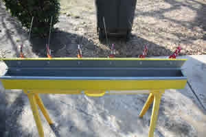
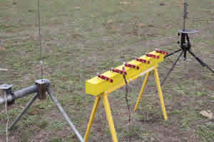
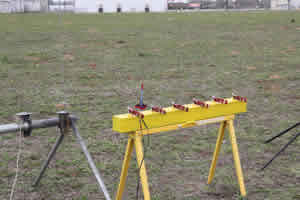
My intention all along was to develop a series of racks for various types of rockets my club may fly. I wanted to standardize as much of the design as possible. I had decided early on that each rack would be mounted on an identical steel sawhorse. To that would be fastened a "box" that would contain whatever wiring was needed and on the "box" would be mounted the individual launch heads. After looking at lots of different options for the "box", I decided to try using NEMA type 1 electrical troughs. For the MMX rack, I ordered a 4"x4"x48" trough with a hinged cover and a pair of endcaps to go with it. I specified that I did not want knockouts.

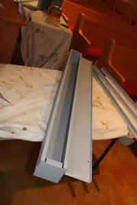
I wanted to go ahead and prime the box and knew that my normal Kilz primer would not be a good choice. Based on some advice, I purchased Dupli-Color automotive white primer and went to work spraying. I quickly learned that while the primer adhered well, a lot was needed for full coverage. I emptied a can and still plenty left to go.
Rather than spend more in primer than the box cost, I decided to brush on some gray primer made for metal applications. I bought a gallon since I have several projects on which to use it and because it was not available in smaller sizes. I brushed on the first coat and let it dry overnight. The end caps were painted as well.
The first coat of gray primer was rather streaky (but much better over the surfaces that had received the white spray primer first) and a second coat was applied to all the pieces. It came out much better.
A day after the second coat of primer was applied, I mounted the end caps. Each one required 3 bolts I used 1/4x3/4 along with a lock washer. When in place, the caps greatly increased the rigidity of the trough.
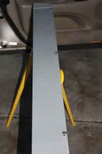
As mentioned before, the base of my system was to be a commercially available steel sawhorse. I chose the one made by Task Force because it seemed sturdy, already had some holes drilled about where I would want them, had adjustable length legs and because it happened to be what was for sale at my local Lowes.
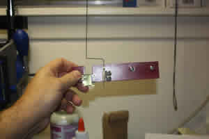
The larger holes in the sawhorse turned out to be just right for 5/16" bolts. I assumed that each base would have a pair of such bolts to fasten the box above. I saw a potential problem, though of the bolt slipping out through the hole while hands were occupied handling the box. I kept asking about some sort of "retainer" to keep them from slipping out. I had just about decided to try and fit a little rubber O ring on the shance to keep it from slipping through when somebody mentioned an "E clip". That turned out to be just the ticket. The bolt was slipped through the hole and the clip was popped into place at the base. It did what I wanted and freed my hands from having to keep the bolt in place while fumbling around with the box.
To hold the box onto the sawhorse mounted bolts, I wanted to use wingnuts that could easily be removed. I also added a fender washer to the system to spread the load out a bit if the assembly were to be picked up by the built in handle on the sawhorse. Since I was not yet ready to mount the box, I just stored the washers and wingnuts in their eventual place of residence.
The bolts on the base are spaced 30" apart so I drew a light line down the centerline of the bottom of the trough and made marks for the bolt holes at that spacing, centered between the ends. The holes were then drilled with a 5/16 bit.
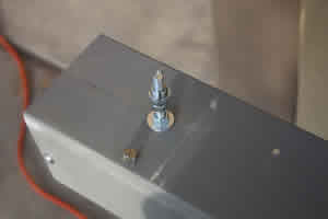
The system was now ready for me to test fit the box on top of the support. As such, I undid the wingnuts and removed the fender washers and was pleased to see that the bolts did not then fall out. So far, so good. I set the box on top and the holes lined up the the bolts...mostly. There was a bit of tightness at one end and the box was forcing the bolt to lean. For grins, I put on the washers and wingnuts and tightened it down part of the way. I then lifted the rack by the carrying handle and it seemed the idea was sound so far but needed a little more work.
One of the things I noticed is that the bolt stuck up farther than I liked on the inside of the box. I decided to use a 3/4" length instead of the full inch. Accordingly, I popped the e-clip off and substituted a shorter bolt. I had also noticed that the bolt tended to turn as I tried to tighten the wingnut. To remedy that I added a star lock washer under the bolt head.
Another problem I noticed is that I must have gotten the spacing for the holes in the box just a wee bit off. On
bolt was tilted to an angle when the box was put one and the nut could not be completely tightened. I tried to fit a
nibbler into the hole but the head would not quite fit so I took a round file and opened it up a bit. I was then able
to slip the head of the nibbler in and took a single bite out of the hole to let the bolt sit more upright. The box was
then put back into place and this time it went down flush and the wingnut took held it flat.
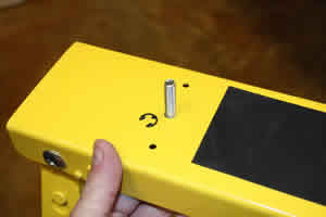
Another thing I wanted to change was the screws that held the hinged cover closed. These were simple screws that I KNEW would pop out and be lost in the field since I wanted to be able to use the box for storage. As such, I ordered some knurled headed screws from Grainger to replace them. I also ordered some split rings to keep the screws from pulling all the way out of the lid. When they came in, all three screws on the cover were replaced.
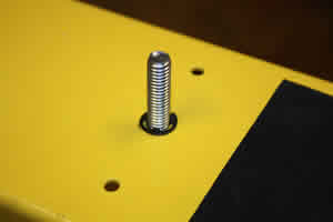
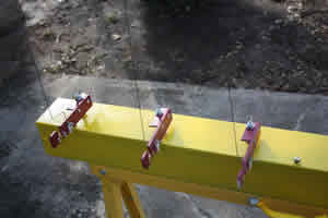
I had decided that the rack would have 6 launch pads spaced 8" apart. This was tighter than I liked but I didn't want the box to be longer than 48" longs for transport. I drew a line down the center of the cover and marked 6 places evenly spaced between the 2 ends. I then drilled 5/16" holes at each station.
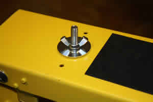
The basic support of each of the heads was to consist of a 2" long, 5/16" bolt. I added a washer to distribute the force and a lock washer to keep the bolt from spinning as the exposed side is manipulated. To hold the bolt fast from the top side, another washer and and nut were placed and the assembly tightened down. A pair of nuts was then put onto the upper side and turned down approximately halfway. The purpose of the twin nuts is to be able to lock them against each other and set the height. Next came a pair of SAE washers and a wingnut. The washers are to sandwich the actual launch head. This process was repeated for all six stations.
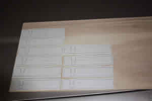
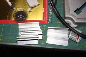
As the actual base and box were being built, I kept working on the design of the launch head, making some changes based upon the original prototype. On the next set of prototypes, I used plywood, a much more durable product than balsa but the trade off is that it does not whittle as easily to make adjustments. I printed up new templates for 10 heads rough cut them with a jigsaw, sanding them down to the outer profile. The notch for the igniters was rough cut with the same jigsaw; there was little uniformity except that I (mostly) stayed within the lines. Finishing down to the lines was done with a combination of X-acto, file and sanding stick and eventually, they were all pretty standard.

An issue that had not been addressed in the previous prototype was the securing of the MMX launch rod. I wanted something more secure than just a hole drilled into the plywood. I wanted the head to retain the rod. I came up with an idea and ran it past several people with much more mechanical experience than me. The answer I kept getting was that "it might work; try it and see." That turned out to be some work and an excuse to acquire some new tools.
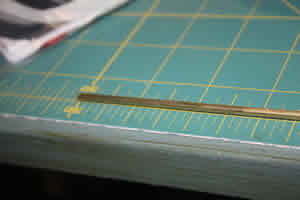
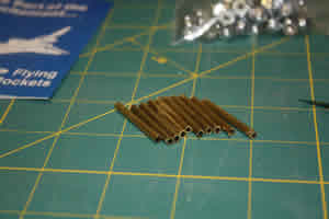
I bought a 3 foot length of 1/8" brass tubing to receive the rods. A cut off wheel on a Dremmel tool was used to cut 10 pieces, each an inch and a quarter long. There was some sloppiness here and some turned out longer and some shorter but, in general, their length was the same as the depth of the launch head.
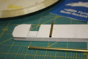

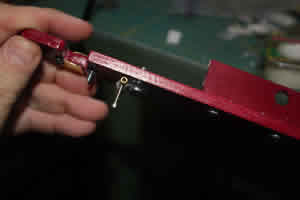
A guy at Quality Fasteners, a local screw and bolt place, gave me the idea for securing the brass tube in place. Up until now, my mind had gone off in a completely different and much more complex direction. For each piece of brass, I obtained 2 nylon harnesses that seem to be designed to retain wire. Each was sized to hold an 1/8" rod and be held in place with a #8 bolt or screw. I place them by eye and used a pen to mark the holes for drilling. The keepers were then bolted into place with nylon locking nuts holding them fast on the opposite side. I found that by not tightening them down all the way at first, I could slip in the brass tube and eyeball it into place. When tightened, the keepers work together to keep it straight.
The next part was the tricky and the iffy part. I wanted a set screw that could be turned by hand that would keep the MMX rod in place. The smallest suitable screw I could find was a #2-56 which had a little head on it that I could thumb tighten. What I did not know is if I could drill the holes through the brass and have enough material to hold a thread. Added to that, I had never used a tap or die in my life.
I set up the proper drill in my Dremmel press and realized that I could much more easily keep the brass tubing straight by leaving it mounted to the launch head. Strangely enough, I managed to drill each of those little hole without having to cut any more tubing. Then came the moment of truth. I took out the tap and started to thread it into the hole. It seemed to bite and the threads seemed to take. I removed the tap and tried the screw. It threaded fine. Best of all, it securely held the MMX rod in place!
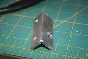
To mount the launch heads onto the racks, I decided to make a mount of of 1/8" x 3/4" aluminum angle (L1/8x3/4x3/4). I purchased a 36" length from Lowes and marked sections 2.5" long. The first of the 10 mounting brackets was cut out with a hacksaw. That got old very quickly and a Dremmel cutoff wheel was used to slice the rest.
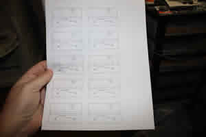
Considerable time was spent with the 10 "2nd prototypes" moving the hardware around and trying to come up with what I thought of as the best arrangement. Finally, I got things settled in my mind and took measurements to transfer to a CAD file for the final template. I generated one set of templates for the launch head and another for the mounting brackets.
The final launch head template was printed out and applied to the 1/4" plywood with a glue stick. As before, a jigsaw was used to cut out the rough blocks. Also as before, a sander was used to reduce the rough blocks to the final external outlines. The igniter notches were rough cut with the jigsaw and finished with files and sanding sticks.
Similarly, templates for all the mounting brackets were printed, cut out and taped into place on the aluminum brackets. All of the 5/32" holes to mount the brackets to the heads were then drilled. When that was done, I randomly tried a few of the brackets with a few of the heads to make sure things were lining up as I thought they should. It was then time to drill the holes for the 5/16 mounting bolts. Since these were quite a bit larger in diameter, I drilled a small pilot hole first. The full diameter holes were then drilled. With that done, the mounting brackets were complete and the templates and tape were stripped away.
The heads had all of their 5/32" (#8) holes drilled followed by the 7/64 (#4).
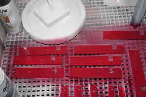
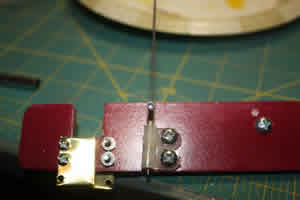
I had always intended to paint this system and decided that the first coat would go on before the next step in assembly. The templates were stripped off and balsa filler coat was applied to all of the plywood heads to fill some of the grain. All of the brackets were then primed with white Dupli Color primer. The launch heads were likewise primed. Everything then got sprayed with a coat of red.
When the paint dried, things began to move more quickly, especially since most of what was left just involved assembly line acts that had been done before. The clips to hold the rod receivers were loosely bolted into place. The receivers that had been fabricated for the second prototype were retained and fit into the clips. Once they seemed straight, the bolts were tightened down. The mounting brackets were then bolted into place and all that was left was to take care of the electrodes, the launch rods and put it all together.
The key to my whole system was the electrode system to handle igniters for MMX. OF course, this is where I ran into most of my problems. My first prototype had worked for ignition and holding the igniters in place but was not very durable, was unwieldy an and a royal PIA to mass produce. I had intended for the electrodes to be connected directly to the launch system in place of the normal lead wires. One of the revelations that came to me is that this would violate my intention of interchangeability between racks; in a pinch, I would not be able to use the MMX leads for another pad or vice versa. Then I realized there was no reason to get rid of the electrodes. I would just have the clips connect them. That way the clips would still be present for other sorts of launches if needed.
I rethought the electrodes and was frustrated by trying to electrically isolate the pair. I had visions of a sheathed, insulated bolt to hold them in place but quickly found that there was nothing existing that I could find to use. I did not want to rely on wood screws that might pull out and the project languished while I tried to figure what to do. Eventually, I realized that the electrode could be bolted on just one side and still stay in place. I just added a bit more material to one side for the holes. Since the electrodes would go on opposite sides of the head, they would clear each other. I drew up a template and printed it out.
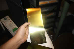
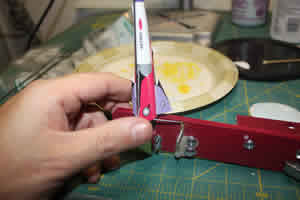
Another change I made on the modified electrode was to choose a thinner gauge of brass. Instead of using strips, this time I bought a sheet of 0.01" thick stock. I taped the template to the brass sheet. I tried several different methods of cutting the brass along the lines, mostly involving a Dremmel cutoff wheel with poor accuracy results. I then found to my surprise that kitchen shears worked better than anything else as long as SHE WHO MUST BE OBEYED did not catch me using them.
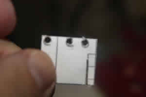
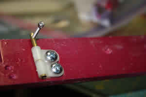
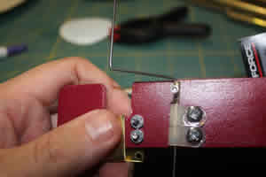
The brass blank with template affixed was then set on a piece of scrap (an old head prototype) and a Dremmel drill press was used to pierce the three holes in the electrode. I should mention here that two of the hole were for mounting and the bottom hole is to give the igniter clips a better grip for connecting.
With the piece drilled, some needle nose pliers were used to bend some contacts for the top surface of the electrodes. I learned that the brass was too soft to want to bend nicely along the marked lines. The electrode was then mounted onto the head with some #4 brass screws and nuts. Several things became immediately apparent. My drilling of the holes with a hand drill had been sloppy and the mounting holes were not in line; the flexing of the drill bit I had noticed in the press was enough to throw things off; and it looked like I was going to have to start again.
After apologizing to the cat for my string of expressions learned in the USN, I tried another blank and got about the same results. This time I noticed that the bit had slipped and flexed even more than before. With my club launch fast approaching and the promised debut of this thing, I had to make some concessions.
I gave up the idea of the bent contacts for the original MMX style igniter (at least temporarily) and cut the electrode blanks to be a bit narrower. I still had some slippage problem with the press but it was less severe when I used some pliers to try to take all of the bends out of the blank. After a bit, a pair of serviceable electrodes were cut and affixed to the head. A little messing around showed that I had something that, while not yet perfect, was serviceable and seemed likely to be better than what I had before.
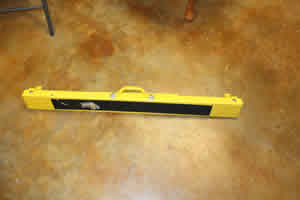
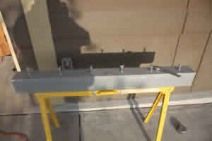
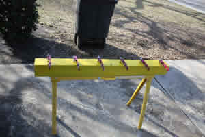
In the meantime, the base and box were undergoing their final steps. I masked off the head supports and the
fastening screws with masking tape in preparation for the final painting. The box was then
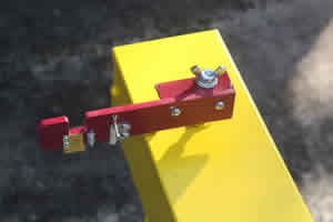
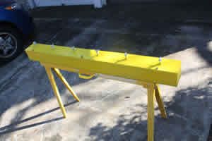 sprayed with 2 coats of yellow Krylon. This was a paint that I got in an auto shop and is supposed to be very hard.
It also dried very fast. The next day I gave the box another 2 coats of yellow to improve the quality of the coverage;
that gray primer was hard to cover. I probably would have given it another coat but I ran out of paint. The base and
support seemed to be done at this point.
sprayed with 2 coats of yellow Krylon. This was a paint that I got in an auto shop and is supposed to be very hard.
It also dried very fast. The next day I gave the box another 2 coats of yellow to improve the quality of the coverage;
that gray primer was hard to cover. I probably would have given it another coat but I ran out of paint. The base and
support seemed to be done at this point.
I was in the home stretch now. I cut out a big stack of electrode blanks and drilled them out. They were then mounted to the heads and I had some spares left over just in case. With that, I had 9 heads ready to go. I had planned for 10 but one of them disappeared someplace along the way. All that was left was the launch rods and to fit things together.
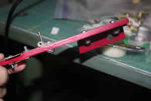
The rods were fabricated from 0.047 music wire. I cut the 36" pieces in half to give 18" segments. The rods were bent at a right angle 1.5" from the bottom giving that much length to fit into the receiver. 1.25" farther along, the rods were bent back to vertical. This gave a straight shot over the igniter slot. Things seemed to line up right and I was feeling pretty pleased with myself. The rest of the rods were then bent into shape.
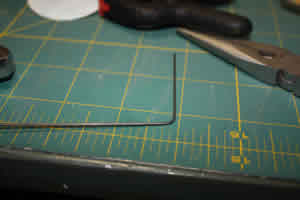
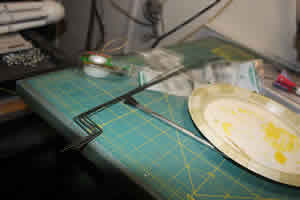
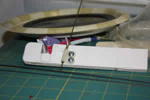
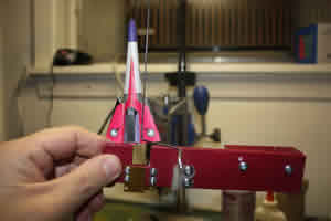
Lucky for me, I had an MMX Vulcan sitting handy and was able to put it on and see how things lined up. It did fine!
I was looking forward to trying out the new rack at my next club launch but rain made our field unusable. I used the sunny day to try fitting the heads to the rack and see how it went.

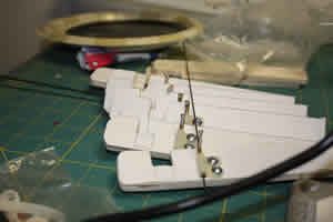
The first step of the mounting was to remove the winguts from the head mounting posts. The heads were then slid onto the bolts and secured with the washers and wingnuts. To get the full effect, I mounted the launch rods. Each seemed to have the proper reach.
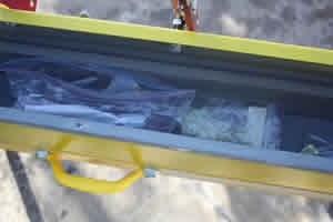
The system was designed so that it could be opened in the field if needed to retrieve extra parts. That means it also stores the rods and heads when I started to break it down. It was ready for the field test.
Finishing:
The finishing of this rack has mostly been covered in the build but here is a recap.
The sawhorse base was left its original yellow. Everything else was primed. The box was then sprayed yellow and the launch heads were painted a dark red.
In time I expect this system to acquire some labels, additional capabilities and wanted to leave my options open at this point.
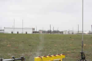
Flight:
I advertised the availability of a new MMX rack to my club and solicited everyone to bring
out their MMX rockets to give it a try. Pretty much as expected though, I was the only one of the Alamo Rocketeers who
had any MMX rockets and I only had two with me. One had never flown before and it was destined to have its maiden
flight coincide with the maiden launch of the new system. That would be my MMX Centuri Vulcan.
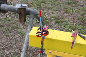
For an igniter I used the Quest variety without the pyrogen. I straddled the leads over the electrodes and clamped the igniter in place with a clothespin normally used as a rod standoff. I tried to make sure the igniter itself was at the right height for the the rocket to set upon.
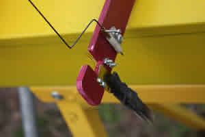
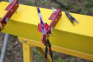
As I tried to set the rocket in place, I noticed that the wooden clothespin holding the igniter in place tended to slip a lot. Then I realized that I could probably do without the clothes pin and use the alligator clips to hold the igniter in place and make contact with the electrode. The rocket and the rack then spent some time service as a static display before it was actually used. When the time came, though, the motor ignited instantly and the rack performed as wished. The flight was unstable but I could not blame that on the rack.
The next victim to be launched on the new rack was a Fliskits Dead Ringer. Using the clips as before to secure the igniter, it was set in place with little or no fuss. When the launch button was pushed, this rocket too took to the air instantly and had a good flight except for the loss of the nose cone. Unfortunately, that loss precluded any more test flights for the new rack that day.
Summary:
This rack accomplished most of what I set out to do but I already see room for improvements
and modifications. I hope to set it up for a few flights at an upocomming Freedom launch and then will consider some of
those modifications.
This is not a light system but that mattered less to me that its durability and ease of use. So far, I am happy in those respects.
Amazing Transformation:

Other:
Persons interested in keeping up with this project as it evolves can follow it
here.
Sponsored Ads


 |
 |