Sirius Rocketry Refit USS Atlantis
Sirius Rocketry - Refit USS Atlantis {Kit} (S-0010)
Contributed by John Lee
| Construction Rating: | starstarstarstarstar |
| Flight Rating: | starstarstarstarstar_border |
| Overall Rating: | starstarstarstarstar |
| Diameter: | 1.33 inches |
| Manufacturer: | Sirius Rocketry  |
| Style: | Futuristic/Exotic, Upscale |
Brief:
According to my records, my Refit USS Atlantis has been sitting in my build pile for about a year. That jives with my
memory. It was one of the first kits I ordered and it has been intimidating me ever since. I really wanted to build it
but I wanted it to look good too. Finally, I decided to give it a try, not because I think I can do it justice but
because I want it so bad. Besides, I'll never develop the skills if I don't actually try.
Construction:
Construction on this one started out as all such projects should but too many do not. I gave the instructions a
thorough reading. That certainly ratcheted up the intimidation factor. Don't get me wrong, the instructions are well
written, very thorough and chock full of helpful hints and tips, but they did confirm that this was going to be an
intensive build.
The first actual build step is the building of the motor mount. I made the motor tube as directed, located the centering rings and engine hook and came to a screeching halt. I searched through the bag and the instructions and found no mention of a thrust ring. Neither did I find the actual ring. It may not be needed but, I like them. I have a few rockets that have omitted them and always notice wear where the engine hook is used as the sole means of blocking the motor. Accordingly, I cut a ring off of a spent Estes E motor and used that as a thrust ring, mounting it with yellow glue and spacing it with a spent D casing.
With the thrust ring in place, I cut the slit for the engine hook and then glued on the three centering rings. The forward and aft rings each have a notch. The forward one allows passing of a Kevlar® thread and the aft one accommodates the engine hook. The middle ring has no notch and is located at the midpoint. The end rings were mounted flush with the ends of the motor tube and all were secured and filleted with yellow glue.
After the glue on the motor mount is dry, the instructions call for the fitting of a Kevlar® harness around the motor tube. The end of the Kevlar® is then fed through a notch in the centering ring. Instead of doing this, I decided to add a baffle system and anchor the recovery system to that. I chose a FlisKits BAF-55.
Since there was no recovery system associated with the motor mount to worry about, the next step was to actually install the motor mount into the main body tube. It was secured in place with yellow glue and with the aft ring flush with the aft end of the tube.
The kit came with a wraparound fin marking guide. I generally prefer these to the end alignment guides that some favor. Sirius has gone a step further than most of the competition though. Theirs is printed on its own sheet. You do not have to butcher the instructions to use the guide.
I cut the guide out (you still have to do a little trimming) and wrapped it around the BT. I aligned the belly centerline with the engine hook and taped the guide an 1/8" forward of the end. I then transferred the lines to the BT and labeled them. I slid the guide off for the time being, as it would be needed again in a later step, and all of the lines were extended the length of the BT using a door frame for alignment.
With the lines extended, I again slipped the wraparound guide onto the BT and ensured that its marks lined up with those on the tube. This time the guide was taped in place flush with the end of the tube. The purpose for putting it back on was to use it to cut the slots for the warp engine pylons.
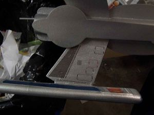
To ensure the cuts would be straight, I taped a steel ruler along one of the lines for the cutout. Then using multiple passes, a razor knife was used to cut the BT. You must be careful not to cut too deep and penetrate the motor tube. When one line was cut, I repositioned the ruler and cut another. Finally, all that was left was the very short cut at either end of the slots. I cut these by simply inserting the razor knife until its width completed the slices. These are by far the straightest cuts I have made in a tube to date. The guide was then removed.
The first of the fins to go in place is the belly fin. It is actually composed of 3 pieces of plywood. The first central piece is the largest and has a notch in the leading edge to accommodate a dowel. The other two pieces have the same lower profile but only extend to just above the slot for the dowel. Taken together, they form a slot for the dowel.
The center fin is installed first. I used a needle to prick a set of holes along the line it was to be mounted on. This was so that the glue could form "rivets" that penetrate the BT. I then put some yellow glue on the root edge of the fin, pressed it place and immediately removed it. I then let both glue trails dry so that I could form the double glue joint. When dry, I applied some more glue to the root edge and carefully placed the fin. The instructions warn that you should not try to form a fillet at this point.
The reason you are warned not to fillet the fin yet is that the two outer pieces still have to be applied. When the fin was dry, I applied glue to the interior face of the outer piece and the root edge and pressed it into place on the central fin. I noticed that both of my side pieces were ever so slightly warped and did not want to sit flat against the central piece. I could find none of the clamps that are hidden around the disaster area I call a workshop but I did notice the battery leads to my battery charger. They did the clamping just fine.
The battery clamps came off after a day and it was time to insert the wooden dowel antenna into the pocket formed by the two side pieces and the center piece. It was glued in place with yellow glue and periodically checked to make sure that the dowel was aligned with the BT and parallel to the BT.
The dowel antenna was followed by two rounded decks, one on either side of the tail assembly. They too were fixed in place with yellow glue.
Another, longer dowel is provided as an antenna that sits on the tail assembly. This was put in place with yellow glue. Note well the side that the instructions have you mark: I marked as indicated and then made an "assumption" and glued it on backwards. Fortunately, I discovered my mistake before it has set up and was able to correct it.
The dish antenna is up next. It is an oval disk with a notch in one side to accommodate the first dowel antenna mentioned above. The disk is glued to the 3 layered tail assembly and helps to support the dowel.
All of the wood assembly up to this point had been fairly easy, but I was worried about the next step: inserting the fin/engine pylons. These were to go in the slots I had cut earlier. I was confident that the slots were in the right place but was worried about alignment. The engine hook was not perfectly centered in the slot of the centering ring and when I had sighted along the tube, the asymmetry tended to throw off my perceptions. This rocket would not work in my Art Rose fin jig so I had to do it by eye.
I decided to use 5 minute epoxy for this step and do the pylons one at a time. Accordingly, I mixed a small batch and began to ladle it into the slot. I then inserted the pylon and did my best to ensure it was at the proper angle to the tail assembly. When the epoxy had set, I mixed another batch and did the same for the other side. When both had set, I mixed a third batch and used it to fillet the joint with the outer BT. They turned out to be easier than I had feared.
After the pylons were in place, I turned to what I thought would be another easy section, the two side decks. There was nothing really difficult about them except that there was a slight bow in the wood. One is applied to each side of the BT. For this, I used a safety pin to drill rivet holes along the application line and put them on with a double glue joint of yellow glue. I actually started at one end and held that in place until the deck would not move. When stable, I gently bend the wood to apply some more glue and then set the remainder in place, holding it until it was dry. The process was repeated on the opposite side. It turned out not to be difficult, but it was tedious.
From the side decks I turned to a simpler task, however, it was the first one involving any of the vacuum formed parts. The top deck is plywood and extends most of the length of the BT. On the deck, however, is mounted the bridge, reminiscent of the bridge of the Star Trek Enterprise. This is vacuum formed plastic.
The instructions suggest that you use a sharp pencil to trace around the vacuum formed parts. This makes it much easier to see the line along which cutting should occur. I then used an X-Acto knife and made about 4 passes to get the part cut out. Sandpaper was used to clean up the edges and to make sure of a flat mounting surface. The bridge was then mounted to the wood with a very small application of tube type plastic cement.
In addition to the two dowels provides for the tail assembly, there are 2 more long ones to serve as conduit. These were easily applied along the marked lines with yellow glue.
The launch lugs came next. The kit actually came with one and instructions to cut it into a longer segment and a shorter one. The shorter one was then glued in place at the back of one of the side decks and the longer one in place even with the aft end of one of the conduit dowels.
By the time the lugs were in place, the bridge was sufficiently dry so that the top deck could be glued into place. I again drilled rivet holes along the length of the alignment line and glued it in place with yellow glue.
The warp pods of the engine derive their strength from a pair of body tubes glued together inside of each pod. Each pair consists of a shorter and a longer tube. Each pair is glued together with the forward edges aligned. Yellow glue was used.
The vacuum formed warp pods were cut out in the same manner as the bridge and sanded likewise. A pair of the tubes was then set in place in the plastic and glued with a small bit of tube type cement. When dry, the opposite side of the pod was glued on with liquid type plastic cement.
Then came the most tedious part of the whole build. The edges of the pods were sanded down. Periodically, this would "break into" the glue joint and the assembly would have more of the liquid cement applied and tape would be put on to hold it closed until it dried. Then the whole process would be repeated over and over again until the join lines disappeared. Eventually, I got to the point where I did not want to remove any more material but still had some fairing to do and putty was used to build these places up. That resulted in even more sanding.
When I was satisfied with the pods, I needed to cut the slots for the pylons. An X-Acto blade was used in multiple passes to cut out the plastic. The process was continued until the tubes were broached and cut as well.
The warp engine pods were attached to the pylons with 5 minute epoxy. I did one side at a time and mixed a small batch. This was ladled into the slot on the pod so that it would cling to the area where the pylon would hit the opposite wall of the tube. The pylon was then slid into the slot and held straight until the epoxy set up. Another small batch of epoxy was then mixed and used to fillet the joint between the pylon and the outer edge of the pod. When dry, the opposite side of the same pod was filleted and the entire process was repeated for the opposite engine.
PROs: Not as difficult as it looks...and it looks great.
CONs: Vacuum formed plastic takes some time to get used to working with, but it can be done.
Finishing:
Finishing of this model actually started during construction. As the plywood pieces were assembled, they were sealed
with balsa filler coat with rounds of light sanding. This resulted in an exceptionally smooth finish after the fifth
coat. I decided not to try and fill the spirals, although I very much appreciated the advice for a good way to do so in
the instructions because they were barely visible. The quality of the tubes was excellent. The nosecone was a little
rough and I started off by using some balsa filler coat on that as well. After 2 coats, however, it was apparent that
it would need many more and I sped things up with Elmer's Wood Filler. With that, I thought I was ready to prime using
Kilz. I figured the Kilz would fill in any spiral that might be visible.
Accordingly, I set the Atlantis up in the booth and my first problem became readily apparent with the first coating of Kilz. The Kilz brought out a few hairline cracks in the joints between the sides of the plastic warp pods. I realized right away that I needed some more filler.
The second problem became apparent as I went back to my desk and started rummaging around waiting for the Kilz to dry. I found a pair of parts I had forgotten to install. These were 2 plywood rails that are applied to the bottom of the warp pods. I immediately began to seal them with filler coat.
When the Kilz had dried, I gave the rocket a sanding and then applied the 2 rails with 5 minute epoxy. I also applied putty to the cracks.
When the putty was dry, I had to sand it down smooth. The result was ugly but the finish was smooth. After painting, I felt it should look very good.
The rocket was then put back in the booth and given another coat of Kilz. It was then sanded some more.
After sanding, the entire rocket was sprayed with a light coat of Rustoleum Silver Metallic. After the first coat, you could barely tell that the rocket had been painted--it puts out a very fine mist. That was fine with me. Every few hours, or when I could get back to the shop, I would give it another coat and it did build up over time. A total of six coats were applied but they are more like 2 "normal" coats.
After I thought I was finished with the silver paint, I looked more closely and found that there were some unpainted places in the shadows of the intricate woodwork. I sprayed these areas and let the rocket dry for another day.
The first of the trim that I attempted were the rhomboids molded into the engine nacelles. I taped of the edges with cellophane, a big mistake (I should have known better) and paited with Tamiya copper using a brush. There were several problems with this. The main one is that the cellophane did not produce a good seal and there was some leakage. I had a plan for this. The second problem stemmed from my own clumsiness. I fumbled the brush and in my attempts to catch it, splattered some paint. To make matters worse, I also smudged some with my fingers. Much was cleaned up with a paper towel but some copper staining remained. When dry, I planned to touch up using some of the sprayed silver paint, sprayed into a puddle, and brushed on.
I also painted the radar dish and antenna of the superstructure with the same copper.
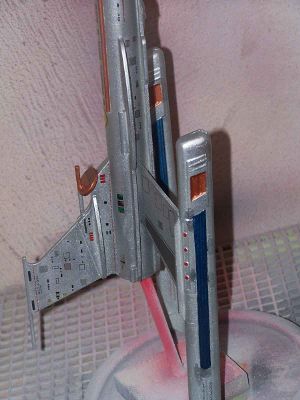
I decided to use some bright red paint to highlight the dots running along the outside of the nacelles. I used Model Master and applied it with a brush.
While staring at the red dots and pondering the relative drying time of acrylics and enamels, I decided that I wanted to do something with the 2 dowel "conduits" on the ventral side. I masked them off and painted them copper as well.
Each of the engine nacelles has an elongated area on each side which you are instructed to paint blue. I masked the areas and brush painted them with Tamiya metallic blue. The color looks good but, on lifting the tape, I found the same bleeding problems I had experienced with the copper. Again, I planned to take care of this problem before adding the decals.
My method for dealing with the paint blunders seemed simple enough. I took the spray can from which the original silver had come and sprayed a big puddle into a paper plate. I then brushed the paint onto the blunders. Coverage was not as good as I had expected. I had to put on a "first coat" and let it dry before tackling it again.
The touch ups with the brushed silver spray did not go perfectly but they certainly improved things. While I was at it, I brushed a bit of blue onto the bridge assembly to make it stand out better.
Before the major task of applying all the decals could begin, I needed to "smooth out" the graininess of the metallic paint finish. This was done by spraying with Rustoleum clear. A total of 3 light coats was applied.
One of the more intimidating parts of this kit is the sheer number of decals. There are four sheets and I knew when I began that my decal application skills are merely adequate. This kit was going to push my limits.
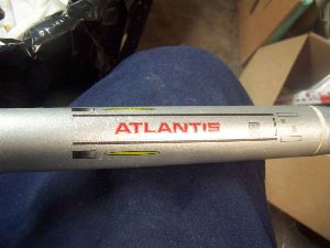
I decided to start simply and add the name and hull numbers to the nacelles. There are four instances of this decal, two in black and two in red. The instructions indicate placement but not color. I elected to put the black on the outer faces and red on the inner.
Since it was on the same sheet, I decided to go with one for the tail assembly next. I cut it out and it was a tight fit. I had to do some trimming to keep it from overlapping the edge.
Next up were the wing pylons. These require 4 decals (each side, top and bottom) and differ only in their being mirror images of each other. They went on without too much fuss.
The upper deck, aft of the bridge is one long decal. To look right, the "bull's eye" needs to be centered in the circular section. This sounds easy but there is some asymmetry which makes it just a touch more difficult that might be imagined. The decals forward of the bridge went on with the same attention to the misleading asymmetry.
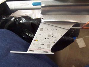
The tops of the side decks each got a decal and the bottoms got a longer version. One of them had to be trimmed to fit around the launch lug.
The tail assembly had already gotten its main decal, but the instructions provide for another one on each side higher up on the 3-ply area. For me, this was confusing because it was obvious that the decal would not fit as outlines, and I don't mean minor trimming here. The lower part of the decal has to be cut off and applied below the horizontal projection. This is not difficult but it gave me pause because everywhere else, the decals were marked with a dotted line where they were supposed to be cut and this one had no such dots, leading me to the conclusion that I was not understanding something. I finally cut it and applied it. Whether I am correct or not, I am satisfied with the result.
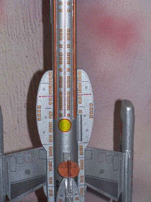
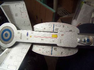
The antenna dish got a grill pattern over its top half. On the forward section of the BT, from the bottom, there are 3 principal decals. The aftermost features a yellow circle and more of the patterning that has predominated on the bottom of the hull. Near the nosecone there is a pretty cool looking Atlantis logo. In between these two is a hull number. On the top surface, near the front, goes a much bigger hull number.
With the decals applied on the top and bottom of the rocket, the 2 sides were left to do. These consisted of 3 longer decals on each side forward of the side decks and then a few small "detail" decals. Several were just logos and one on each side consisted of 3 colored squares.
After all the decals were dried, I set the Atlantis up in the spray booth and began applying light coats of clear. I gave it a total of 4 coats. With that, the Atlantis was ready to fly...the next day.
PROs: This is a good looking rocket but the decals take it to a whole new level. They really make a superior kit awesome.
CONs: getting those nooks and crannies painted can be hard but the effort is worth it.
Construction Rating: 5 out of 5
Flight and Recovery:
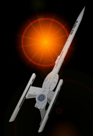
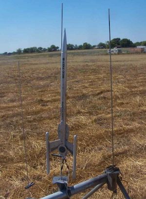
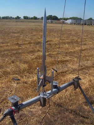
The day of the maiden flight of the Refit Atlantis arrived and it was prepped with a D12-5. People wanted to see this
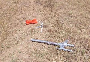
one. On takeoff, it weathercocked a bit but was very stable. It ejected and recovered not far away. I wanted to try it
on something bigger.
A video of the flight can be seen here.
The landowner was kind enough to open a gate and let me on his property but warned me about Sweetie. It turns out that Sweetie is a dog but I was not worried because Sweetie was a dachshund. Sweetie seemed...sweet until I went past the gate and then she became a hellhound. It's humiliating, really, I never thought I would ever meet the dachshund who could outrun me. I bet she was funny looking, but I was too busy looking where I was running. At least I got my rocket back.
A video of the second flight can be seen here, but don't blink.
 PROs: This one is bound to look good, no matter what. Seeing it in the air is even better.
CONs: It is prone to weathercocking but that is the hazard of all that area aft. Without it, it would just be another rocket.
Flight Rating: 4 out of 5
Summary:
I love this one. It looks cool. It was challenging but not impossible. I am actually proud of it, not something I say
about too many of mine in terms of appearance.
I'm glad I waited to get started...I didn't have the skills to build it when I bought it. I hope it has a long career.
Overall Rating: 5 out of 5
Other Reviews
- Sirius Rocketry Refit USS Atlantis By John R, Brandon III (September 29, 2011)
The Refit USS Atlantis is a classy update-upscale of Estes' old USS Atlantis exotic starship. The old one flew on 19mm motors, this one is set up for 21mm. It's mostly a plywood and cardboard-tube kit with some vacuum-formed plastic parts as decor. I have to brag on Sirius' customer support. I ordered the Atlantis kit on the first of September and their website reported it shipped ...
- Sirius Rocketry Refit USS Atlantis By Drake "Doc" Damerau (March 26, 2007)
( Contributed - by Drake "Doc" Damerau - 03/26/07) Brief: I saw that Chan Stevens, a top-notch builder and reviewer, already reviewed this kit but I wanted to add to it by going a little further into the construction and offer more construction details. It’s not a “second opinion” review, rather one to complement Chan’s review. Construction: Engine ...
- Sirius Rocketry Refit USS Atlantis By Chan Stevens
Brief: Inspired by Star Trek, this futuristic spaceship design will draw a crowd at the pad and flies surprisingly well. At $60, it's a bit on the pricey side, but it is made with quality components and design and is challenging and enjoyable to build. Construction: I ordered my kit via the Sirius Rocketry website with their flagship Saturn V kit. There was a delay of a couple ...
 |
 |
Flights
Sponsored Ads


|
|