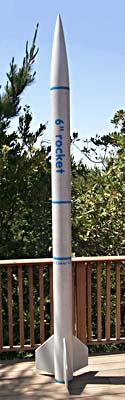
Scratch Generic Rocket Original Design / Scratch Built
Scratch - Generic Rocket {Scratch}
Contributed by John Coker
| Manufacturer: | Scratch |
Note: This is a slightly condensed version of all the information that John has produced for his Level 3 project. Visit his site to read the additional information and enjoy additional pictures.
 For my
next trick, a rocket which will actually be used for my certification! I've
been in this hobby almost a year and it seems time to start building my level-3
certification rocket. I wanted it to be a scratch-built rocket, not a kit. At
first, I planned to do an upscaled Alpha III as my certification rocket, but
both my TAP reviewers pointed out that the fins would be very fragile and it
was better to do a simpler design.
For my
next trick, a rocket which will actually be used for my certification! I've
been in this hobby almost a year and it seems time to start building my level-3
certification rocket. I wanted it to be a scratch-built rocket, not a kit. At
first, I planned to do an upscaled Alpha III as my certification rocket, but
both my TAP reviewers pointed out that the fins would be very fragile and it
was better to do a simpler design.
If I'm going to go with something simple, I should do something very simple, a "three fins and a nose cone" rocket. I decided to build such a simple rocket, it would be a generic rocket!
A generic rocket would have three clipped-delta fins, would be use dual deployment, breaking about the middle of the rocket. I decided on a 6" airframe as a size that is easy to work with. As a good rule of thumb, I used 20:1 length-to-diameter ratio, yielding a 10' rocket. This is still a handy size, while being large enough to handle an M1939 (full M). Level-3 certifications cannot be multi-stage or use clustering so I planned a single 98mm motor mount.
I was lucky to find two TAP members early on to help me make sure I did this right. Scott Bartel and Pius Morozumi agreed to help me out. I can meet with Scott when I go down to ROC to launch and Pius lives in the Bay Area, about an hour to the south. I am very glad these two fine gentlemen and master rocketeers have agreed to help me. Karl Baumann (Mojave Desert High Power) attended the MudRock launch where the first Generic Rocket flew and agreed to sign my forms. Thanks Karl!
I was even more lucky to have Pius close by and willing to give me advice in the design and construction of the rocket. One fantastic thing which came out of this was the refinement and publishing of the kitchen table vacuum bagging technique developed by Pius and William Walby. Also, Pius helped with rocket design rules of thumb and gave guidance throughout the project. Thanks Pius!
Design Construction
 The deeper humor in the name
Generic Rocket is that it's really not generic at all. Careful rocket
design, carbon fiber reinforcing, dual deployment and advanced electronics make
this a "state of the art" hobby rocket. Note that this isn't intended
to invent anything new, but use the best of the current techniques to produce
an efficient and reliable rocket.
The deeper humor in the name
Generic Rocket is that it's really not generic at all. Careful rocket
design, carbon fiber reinforcing, dual deployment and advanced electronics make
this a "state of the art" hobby rocket. Note that this isn't intended
to invent anything new, but use the best of the current techniques to produce
an efficient and reliable rocket.
The first step in this process was to design a 6" rocket using the rules of thumb for rocket building. The rocket is 20 calibers long and the fins are at the aft and are just large enough to provide stable flight. I actually designed this rocket in Apogee's excellent RockSim 4.0. This program allows you to assemble the components to form the rocket, then gives you estimates of weight and CG so that you can do stability checking and flight simulation before you've built your rocket.
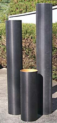
The tubes were supplied by Red Arrow (first airframe) and Giant Leap Rocketry (second airframe) and are both flexible phenolic. The couplers, bulkheads, fins and centering rings for both airframes were supplied by Giant Leap Rocketry. Thanks Ed! The decals were custom made by Randy Brust.
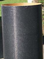
I'm particularly pleased with the airframe tubes. Using the simple and inexpensive kitchen table vacuum bagging (FoodSaver) technique, the tubes were all covered in 5.7oz. carbon fiber and then a 3.6oz. S-glass sanding veil. And don't the tubes look stylish all dressed in black!
 My
current favorite airframe material is "flexible phenolic" (from Giant
Leap and Red Arrow) laminated with cloth made with carbon fiber or Kevlar®*
fibers. Kevlar® is stronger, but much harder to work with. Carbon fiber is
a bit difficult, but excellent results can be obtained with ordinary tools and
skill. The airframe tubes covered in carbon fiber and S-glass weigh only
slightly more (¼lb. per foot) than the unreinforced tubes, thanks to
vacuum bagging. Of course, after all that work on the airframe tubes, I wanted
to make sure they were slotted perfectly. I had to update my technique for
cutting fin slots for the larger-sized tubes.
My
current favorite airframe material is "flexible phenolic" (from Giant
Leap and Red Arrow) laminated with cloth made with carbon fiber or Kevlar®*
fibers. Kevlar® is stronger, but much harder to work with. Carbon fiber is
a bit difficult, but excellent results can be obtained with ordinary tools and
skill. The airframe tubes covered in carbon fiber and S-glass weigh only
slightly more (¼lb. per foot) than the unreinforced tubes, thanks to
vacuum bagging. Of course, after all that work on the airframe tubes, I wanted
to make sure they were slotted perfectly. I had to update my technique for
cutting fin slots for the larger-sized tubes.
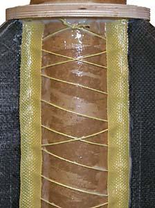
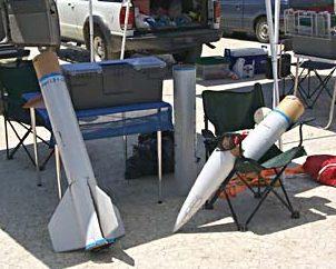
I also wanted to make sure that the fins stayed on the MMT. Pius showed me a technique for lacing the fins around the MMT with Kevlar® thread. As you can see in the picture, I laced the fins on with numerous strands of 1000lb. test Kevlar® thread. And then, I reinforced the joint with Kevlar® tape as you can see in the picture above right. I don't think these fins are coming off!
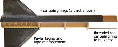
In the picture above, you can see how the internal reinforcing is used. Kevlar® lacing and tape bond the fins to the motor mount tube. Four centering rings are used for strong body tube contact. Threaded rod bonds the bulkhead of the anti-zipper design to the forward centering ring.
The dry weight of the rocket is 27# including the entire recovery system (reasonably light for such a heavily-built 10' 6" rocket). The candidate motors for this rocket are an M1939 for the certification flight and an N2000 for an encore. RockSim calculates the C.P. at 99.3" (Barrowman) and 102.9" (RockSim) and the average is 101.1". I balanced the rocket to determine the C.G. with simulations of the motor weight with the result below:
| Motor | Weight | C.G. | stability |
|---|---|---|---|
| - | 0# | 69¾" | 5¼ calibers |
| M1939 | 20# | 87¼" | 2¼ calibers |
| N2000 | 27# | 88½" | 2 calibers |
The rocket will be quite stable with both the M1939 and the N2000. Note that I had to add ½# to the tip of the nose to gain the C.G.s above.
Airframe
The design of the airframe is simple and intended to be purely functional. The rocket is twenty calibers long and the fins are just larger than minimum for stability. The fins are clipped deltas with the trailing edge angled slightly forward to help avoid landing damage. The intention is to produce a simple, reliable, high-performance rocket. Note that this is a custom design, although everything was done according to standard practice, hence the name "Generic Rocket."
The airframe tubes are 6" flexible phenolic covered in 5.7oz. carbon fiber. Construction uses mechanical means wherever possible and the adhesive used is West Systems epoxy (mostly using 404 high-density filler). The motor mount is attached to the airframe with four centering rings which are screwed as well as bonded to the airframe. The fins are ½" plywood laminated with carbon fiber. They are attached to the motor mount tube with epoxy and sewn to it with Kevlar® thread and then reinforced with Kevlar® tape. The motor mount itself is a single 98mm phenolic tube (this is not a clustered flight). All construction was performed by the flier, with suggestions from Pius Morozumi on many aspects. Thanks Pius!
Safety: There should be no dangers due to design since the rocket is simple and standard. Poor airframe construction could lead to a shred, but the materials and techniques employed are ones known to be leading-edge for high-power rocketry.
Recovery System
The recovery system attachments use U-bolts and 1000lb. quick links. The bulkheads are all ½" "aircraft" birch plywood. The bridles are 1" tubular Nylon® To avoid zippering, the aft section of the rocket uses an anti-zipper design (coupler and bulkhead protrude forward).
Rocketman Pro-XP chutes are used in a dual-deployment configuration. The deployment system will use black power charges to pressurize the airframe and deploy the parachute as is typical for high-power rockets. Drogue recovery uses a Rocketman R24C 'chute and main recovery uses two Rocketman R12C 'chutes.
Note that my first level 3 attempt was done with an almost identical rocket. The attempt was unsuccessful because the main parachutes never fully emerged from the bay. This was due to poor arrangement of the recovery system which has been fixed in the second rocket. The main parachute now ejects from the front of the rocket (the charges are behind the parachutes) plus the parachutes are attached along the bridle, not directly to the airframe.
Safety: A separation or failure to deploy the recovery system would be very dangerous on a rocket this large and heavy. Mounting points for the recovery system use U-bolts instead of eye bolts and bonded joints are reinforced with steel.
Avionics Description
Primary avionics is redundant Black Sky Research ALTACCs, since this has been proven in many flights. Each altimeter will have a separate power source and separate electric matches (DaveyFire 28F), as well as separate black-powder charges. These units will be located in the center section. The ALTACCs are armed from the outside so no additional wiring is needed.
Since the redundant systems are identical, there is a good chance that both charges would go off simultaneously. While the airframe should be strong enough to withstand this, it is clearly a good thing to avoid. One set of ejection charges will include 1" pieces of Thermalite to delay them by about a second.
Safety: Again, failure deploy the recovery system would be very dangerous on a rocket this large and heavy. 100% redundant altimeters should minimize this risk.
Motor
The motor will be the celebrated AeroTech M1939, which is Tripoli certified. Motor ignition will use a DaveyFire wrapped in slivers of Blue Thunder propellant.
The motor will push the rocket using the reloadable case rear closure pressing against the motor mount and rear centering ring. Positive motor retention will use two custom-made aluminum brackets bolted to T-nuts in the aft centering ring. The motor tube is closed at the forward end and no ejection charge will be used.
Safety: Using a well-known pre-manufactured motor should reduce the risk of a CATO or other failure to reasonable levels. A failure to ignite should pose no safety problems, and the motor is definitely powerful enough to lift the rocket. The motor mount/fin can has been strongly reinforced using Kevlar® sewing and lamination to reduce the risk of shredding or losing a fin.
Launcher
The rocket will be fitted with Black Sky Research ProRail guides and can be launched from a standard 6' or 8' ProRail. Three guides will be used: one at the rear of the rocket, one about halfway to the C.G. and one on the altimeter bay (well forward of the C.G.).
There are no special launch requirements and we intend to launch the rocket straight up. Since this is a single-motor rocket, only a standard launch system is required.
Safety: The projected speed of 55ft/s off the rail is ample for a stable flight with this rocket and the loaded weight of 47 pounds is well within the capabilities of the ProRail.
Performance
Rocket design and simulation was done with Apogee Component's RockSim.
Safety: This rocket is a very standard design: three fins and a nose cone so standard stability and performance calculations should yield a close match to reality. Note that the rocket's basic shape makes it very stable so the allowable error for this rocket is large.
Operations
As called for in the TAP Pre-Flight Review, the following pre-flight checklist has been prepared.
- replace batteries and test altimeters
- load 4 ejection charges (apogee 2g, main 4½g)
- attach main recovery airframe with four allen screws
- pack main recovery system and pin nose cone
- pack drogue recovery system and assemble rocket
- build M1939 reload (plugged) and install with retainers
- load onto pro-rail
- turn on ALTACCs and verify continuity (three flashes)
- install igniter and connect to launch system and verify continuity
- return behind flight line
- wait for launch with fingers crossed!
 SUCCESSFUL LEVEL 3 FLIGHT!
July 24, 1999
Black Rock, NV
Rocket - Scratch Generic Rocket
Weight - 47 lbs
Motor - Aerotech M1939
Altitude - 12,889 ft
Level 3 Attempt at MudRock '99
At MudRock '99, it rained the week before the launch, so we weren't able to get out on the playa on Saturday (the first day of the launch, June 5th). We were able to use the gravel quarry, but the recovery area was small and people stuck to smaller stuff. I had meant to fly my level-3 attempt, but I didn't want to do it from the quarry. Instead, I flew the Honest John again, this time on an I357.
I set up my camp right up to the flight line as I got in with the early crowd this time. Proudly, I set up the Generic Rocket against the EZ-Up. Unfortunately, a gust of wind came up and knocked it over, making two small dents in the airframe and a two serious cracks in the P.M.L. fiberglass nose cone. With the unfriendly weather plus the damage to the rocket, I had mentally scrubbed the launch. However, by afternoon it had been dry all day and the wind had come up and it looked pretty good for getting out on the playa. Saturday night I was back in the room repairing the rocket. Bruno's is home to some very strange scenes!
 On Sunday we were
able to get back out on the playa, carefully. There were lots of clouds, but
all white and fluffy and it looked like a good day for a level-3 attempt! The
epoxy was dry on my rocket and a quick sanding made it smooth, although the
patches showed. Because there were heavy clouds, we were all anxious for them
to blow away and everyone was busily getting ready to fly. Next to me, Pius was
putting the final touches an the ARLISS project test rocket. I sat down in
front of the M1939 components to put together my motor.
On Sunday we were
able to get back out on the playa, carefully. There were lots of clouds, but
all white and fluffy and it looked like a good day for a level-3 attempt! The
epoxy was dry on my rocket and a quick sanding made it smooth, although the
patches showed. Because there were heavy clouds, we were all anxious for them
to blow away and everyone was busily getting ready to fly. Next to me, Pius was
putting the final touches an the ARLISS project test rocket. I sat down in
front of the M1939 components to put together my motor.
A break in the clouds finally appeared and Pius and William launched their ARLISS test rocket. They had a beautiful flight and recovery, including flawless operation of all the complex recovery system for the can satellites. When they came back, Pius helped me put my rocket together and take it out to the flight line.
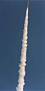
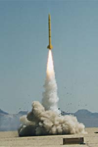
Back to the flight line and a short countdown later, the Generic Rocket was in flight. That M1939 makes a fantastic flame, smoke cloud and roar!
 The flight was
majestic and straight, beautiful to behold--Gotta love that long burn full M.
We lost sight of the rocket about a third of the way through the ascent. No
longer being able to see it, and not sure when apogee was, I didn't use the R/C
back-up to trigger the main. We didn't see any part of the descent, but knew
something was wrong when Sue McMurray, who was following the rocket with a
Walston tracker, said "it's down" after about 30 seconds. Sue and I
went out to recover the rocket and found it about three miles away, severely
damaged.
The flight was
majestic and straight, beautiful to behold--Gotta love that long burn full M.
We lost sight of the rocket about a third of the way through the ascent. No
longer being able to see it, and not sure when apogee was, I didn't use the R/C
back-up to trigger the main. We didn't see any part of the descent, but knew
something was wrong when Sue McMurray, who was following the rocket with a
Walston tracker, said "it's down" after about 30 seconds. Sue and I
went out to recover the rocket and found it about three miles away, severely
damaged.
The main 'chute never fully deployed and the rocket came down on only the drogue. All three sections of the rocket had severe damage, although all electronics survived. We found a nice little hole in the playa where the aft end of the rocket had hit, then fell over. No level 3 this time.
In the post-mortem, we decided that my rigging of the ejection charges was at fault. I should have placed the ejection charge behind the parachute. I had packed the bridle in before the 'chute, expecting it to pull the 'chute out as the pieces separated, but this didn't happen. I could have saved the rocket with the backup system, but didn't use it because I couldn't see the rocket and didn't know when apogee occurred.
At first I was pretty depressed, especially since the flight was so beautiful. But, I will rebuild the rocket and am planning to use the same general design, with some changes to the position of the electronics and deployment pattern. Onward and upward!
Second Attempt at Aeronaut '99
 The
entire airframe was rebuilt and the recovery system was modified to make it
more reliable. Several analyses of the first flight determined three mistakes:
The
entire airframe was rebuilt and the recovery system was modified to make it
more reliable. Several analyses of the first flight determined three mistakes:
- Ejecting the 'chutes into the tube: In the first version, I split the airframe for main recovery at the point where the charges were located. This meant that the parachutes and rigging needed to pull out of the tube after separation. The problem is that the ejection charge itself doesn't push out the parachutes and the lines can get fouled.
- Packing the rigging without bundling it up: I just stuffed the parachutes (folded properly) and the rigging into the tube without folding up the rigging. The rigging got tangled up and never fully emerged.
- Attaching the drogue directly to the anti-zipper bulkhead: I attached the drogue directly to the anti-zipper bulkhead on the booster. The problem with this is that the drogue operates with much lower efficiency and has the tendency to make the rocket rotate.
The Best analysis so far: rocket came down on the drogue too fast and spinning because of the way the drogue was fastened. The main 'chutes tangled with the large amount of loose line (1" tubular Nylon) instead of being pulled out of the airframe because of being pushed into the airframe by the ejection charge and the spinning.
Oh, there was actually a fourth failure: finishing too close before the launch to get a final going-over by the TAP members before flight. Hurry is hard to avoid and in this case, at least some of these mistakes could have been seen when the rocket was laid out on the ground fully rigged.
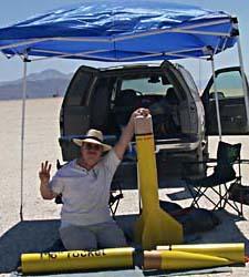
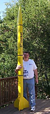
With these problems remedied and the rebuilt airframe (yellow and black this time), I was ready in plenty of time for the Aeronaut launch of July, 1999. To the left you can see Pius and Myself posing with the assembled rocket at my campsite on Saturday morning.
The new rocket ejected the dual main parachutes forward by popping off the nose cone. The main 'chutes also were rigged differently: more line and each section of line was bundled up and secured with tape to make a neat package. Also, the dual ALTACCs were each wired with a separate charge, making two 100% redundant systems. Each charge for one of the ALTACCs was delayed with a short piece of Thermalite to prevent the charges from going off together.
Now, we just had to wait for a break in the gusty winds go head out to the pad...
About 10:30, the winds calmed down enough for the launch and we assembled the rocket and took it to the RSO table. I had a big crew to help me carry the 47lb. rocket and load it onto the ProRail. On the left you can see the people who helped me prepare and set up the rocket: Nevin Loop, Pius Morozumi (making sure the rocket is level), Tom Rouse and Gordon Hom.
 We had
to adjust the rail a bit to give the rocket enough rail and to balance it
correctly, especially with the gusty winds. Just putting the rocket on the rail
takes three people with a rocket this big and heavy (10' 6" and 47lbs.).
But, the wind had died down nicely and the rocket was up and ready!
We had
to adjust the rail a bit to give the rocket enough rail and to balance it
correctly, especially with the gusty winds. Just putting the rocket on the rail
takes three people with a rocket this big and heavy (10' 6" and 47lbs.).
But, the wind had died down nicely and the rocket was up and ready!
Once the rocket was loaded, I had to arm the two ALTACCs. The first time up,
one of them didn't get continuity, so we had to take down the rocket, go back
to my camp, unload and replace the ALTACC. Luckily, the second time they both
armed perfectly.
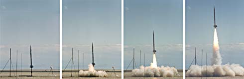
The Generic Rocket took off in light but gusty winds on an M1939. Ignoring the wind, the rocket made a straight ascent into the cloudless sky and the entire flight was easily visible.
The rocket was recovered stretched out in three pieces exactly as intended, earning a clean level 3 certification. Hurray! It flew to 12,889 ft. at a maximum velocity of 1029 ft/sec. and a maximum acceleration of 256 ft/sec². Even Pius and Karl were happy after signing off on the flight and the returned rocket.
Sponsored Ads

, Launch Pad/ Controller, Glue, Four AA Batteries, and Two Engines")


 |
 |