| Manufacturer: | Scratch |
NCAA
Not a Conventional Altitude Achiever
 Background:
For the last two years I have enjoyed coaching in the local youth football
program. Conditioning practices begin the first week in August and the season
includes six regular season games and two post season games, ending in late
October. Well, after three months solid (three practices and a game per week)
of this you can just imagine that football withdrawl sets in come mid-November.
Anyhow, as the season was ending, I had an idea for a football rocket to enter in DESCON 7 but never got the chance to build it. The idea fit the found parts theme perfect so I decided to give it another go.
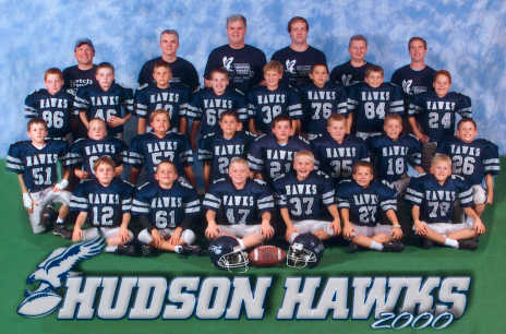
This entry is dedicated to the 2000 Hudson Gremlin Silver Hawk team that I head coached this last season and to my son Eric who volunteered his football to the cause. GO HAWKS!
 Overview:
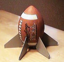
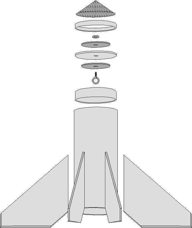
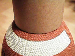
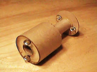
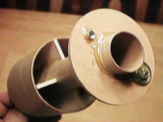
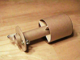
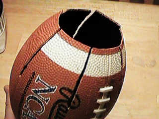
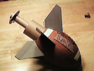
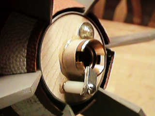
This rocket is a full size plastic/rubber football with a sealed body
tube inserted into one end of the ball. The end of the ball is cut open and
slit to allow it to slide over the body tube and fins (TTB-"Through The
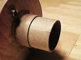
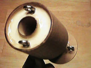
Ball" construction). The motor is contained in a piston assembly which is
forced out the rear of the ball by the ejection charge. There is ample room
behind the piston to insert the recovery system (parachute/shock cord). The
piston assembly is attached to the bulkhead of the body by a picture wire
(similar wire to NCR kits) and allows the ejection gases to escape without the
need for a baffle or wadding.
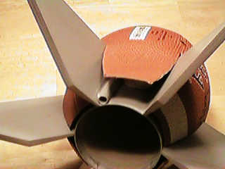
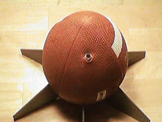
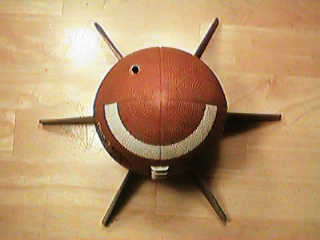
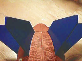
Special feature:
The fins are shaped to force the ball to rotate or 'spiral'.
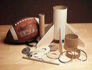
| Body Assembly: (1) Regulation size rubber football (not shown above) (the solid sided type without a separate bladder) (1) 7-5/8" piece 3" LOC airframe (1) 8" piece of 1/4" ID Aluminum Tube (1) 1/4" piece 3" LOC Tube Coupler (1) 3" Bulkhead (or 3"/1.14" CR) (1) 1" piece 3" LOC Tube Coupler (2) 3/16" x 2" Fender Washers (1) 3/16" Eyebolt with nut (1) Approx. 24" Picture Hanging Wire (6) 7/8" x 4-3/4" pieces of 1/8" Basswood (6) Fins from 1/8" Basswood (see below for template drawing) (1) 8oz. BB's or other shapable weight |
Piston Assembly: (1) 7-1/2" piece of 29mm Motor Mount Tubing (2) LOC 3" to 1.14" Centering Rings (4) 1" x 3" pieces of 1/8" Basswood (1) 1-1/2" #10 Screw (1) 1/4" #10 Tee-Nut (1) 3/4" #10 Nylon Bushing (1) Aluminum Screen Bracket (3) 3/16" Eyebolts with nuts (3) 3/16" x 3/4" Fender Washers (1) 9 foot piece of 3/8" elastic |
Preparation:
From the 1/8" basswood:
1) Cut (6) 7/8" x 4-3/4" pieces. Sand each piece with a beveled side
from 0" to 1/8". These are not shown on the exploded drawings.
2) Cut (6) fins to match the template. Round the lead edge.
3) Cut (4) 1" x 3" pieces and set aside for the Piston Assembly.
From the Football:
Use the tube coupler to mark the end of the football for cutting a hole that,
with some effort, will allow the 3" body tube to fit through. It is VERY
IMPORTANT to make sure that you cut the hole centered precisely or the bottom
seams will not line up properly with the base of the body tube. Use the
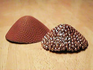
football tip, that you cut off, as a mold to form your 8oz. nose weight using
BB's and epoxy. Set aside for the Body Assembly.
From the Motor Mount Tube:
Cut a 1" piece off the tube and cut to create a coupler that fits inside
the motor mount tube. This piece is not shown on the exploded drawings.
One Piston centering ring requires: Sand the outside edge of ONE the centering rings so that it fits INSIDE the 3" tube coupler.
From a 3" LOC Tube Coupler (stock 6" long):
1) Cut (1) 1/4" piece for the Piston Assembly and cut to fit INSIDE the
3" coupler.
2) Cut (1) 1/4" piece for the Body Assembly.
3) Cut (1) 1" piece for the Body Assembly.
4) Cut (1) 3" piece for the Piston Assembly.
Assembly Instructions:
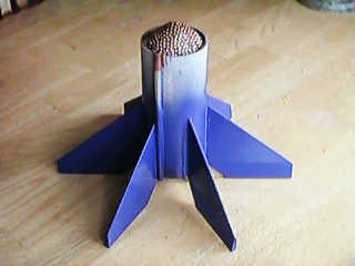
1) Glue the 7/8" x 4-3/4" pre-cut and sanded pieces of basswood to the aft edge of each of the fins and trim the excess toward the root to match the fin shape. The beveled edge should face the lead edge thus forming flaps to cause the rocket to spin as it flies (like throwing a spiral). Make sure that they are all glued to the same side of each fin.
2) Pre-finish the fins to eliminate 'flap' seams and wood grain.
3) Attach the fins to the 3" body tube and fillet with epoxy. You can apply a couple coats of primer to the fins at this point. Set the body assembly aside.
4) Drill two holes in the forward piston centering ring to accept the (2) eyebolts/washers and glue in place with the eyebolts facing the same direction on the ring.
5) Glue the 1/4" resized tube coupler piece inside the front edge of the 3" tube coupler.
6) Glue the centering ring, with the eyebolts facing out (forward), behind this inner coupler.
7) Glue the motor mount tube to the centering ring with the tube extending about 1/4" through the front of the assembly.
8) Sand, test fit and then glue the (4) 1" x 3" pieces of basswood behind the centering ring and between the inside of the coupler and the motor mount tube. Make sure that they are NOT snug as this will affect the shape of the coupler/piston and it may not fit properly in the main body tube.
9) Drill two holes in the aft piston centering ring to accept the eyebolt/washer (shock cord mount) and the t-nut/screw/bracket (motor retention) and glue in place with the eyebolt facing the front side (toward the parts in step #8) and the t-nut facing the back side of the ring. Set the piston assembly aside.
10) Push the 3" body tube (with fins attached) into the football as far as it will go. Make sure the tube is centered and then mark the rear of the football where the fins meet it. CAFEFULLY cut slits in the football to accomodate the six fins. This is best done by cutting a small amount away at a time and slowly working the body assembly into the ball. The front of the body tube should butt against the closed end of the football when you are done.
11) Remove the body from the ball. Epoxy the launch lug (1/4" aluminum tube) to the body tube with the rear of the lug flush with the rear of the body. I glued it against one of the fins to make it easier to cut away the football skin at the point where the rear of the ball meets the body tube.
12) Once the epoxy dries, fit the body back into the football. Carefully cut a hole for the launch lug at the front of the ball. Remove the body tube from the ball.
13) Set the body tube on a table/counter upside down with the launch lug hanging over the edge. Place the 1/4" length of tube coupler to the front (bottom) edge of the body tube, followed by the bulkhead, followed by the 1" length of tube coupler and DO NOT GLUE.
14) Slide the piston assembly into the rear of the body and push it firmly all the way forward. Place the rear piston centering ring onto the motor mount tube and slide it down until it is about 1/16" into the body tube. Mark the position of the ring on the MMT. Remove the piston assembly and epoxy the rear centering ring in place. The piston assembly is completed at this point.
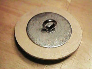
15) Drill a center hole in the bulkhead (if applicable) and attach the eyebolt with the two 2" fender washers sandwiching the bulkhead. Epoxy in place.
16) Paint and final coat the fins.
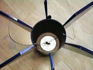
17) Thread the picture wire halfway through the bulkhead eyebolt and twist it a few times. Thread each end of the picture wire through an eyebolt on front of the piston assembly and twist to allow for a distance of (measurement to come)" between the bulkhead and the piston.
18) Glue the 1/4" coupler, bulkhead and 1" coupler (with attached piston assembly) from Step #13 in place. Be careful not to let the piston get glued in place.
19) Epoxy the nose weight to the outside of the bulkhead.
20) Rough up the bottom edge of the body tube. Snugly fit the body tube back into the football and glue the BOTTOM edge seams (along bottom edge of body tube) with epoxy. Once the epoxy is dry, glue all remaining seams with silicone glue.
21) Slide the 1-1/2" #10 screw through the screen bracket and the nylon bushing. Screw this into the t-nut for motor retention.
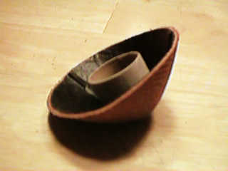
22) Glue the 1" resized MMT onto the inside center of the football end piece that you had originally cut off. For display purposes, this slides into the end of the motor mount to conceal the business end of the rocket.
Flight Specifications:
Finishedweight: 32oz.
Parachute: 30-36" diameter
Recommended Motor: G64-4
Flight Log:
Date: April 29, 2001
Location: Mantua, Ohio
Conditions: Sunny
Temperature: 70-72ºF
Wind: Calm
A beautiful day and perfect conditions for launching this stubby odd-roc. After much prompting from all the kids, "I want to see the football rocket fly", I loaded up a G64-4 RMS and set the NCAA on the pad ready for the "toss". After giving the "heads-up" call, 3-2-1....nothing. "You got a copperhead in there?" The copperhead took the blame but it looked like I just forgot to arm the pad--sheesh! 3-2-1-LAUNCH! WOW! Straight up with a gentle spiral, just like a Montana-to-Rice connection. Over apogee and ejection at just about the right time. Well this is where we had an "illegal downward pass" infraction. The force of the ejection charge broke the picture wire at the bulkhead attachment point on the body. Separation! The chute deployed as planned and brought the piston and RMS casing to a soft landing on the field BUT the football/body/fin section came in ballistic and sounded like a buzz-bomb whistling in.
Believe it or not, even though it is now in 9 pieces, this rocket can and will be rebuilt with a modified recovery system. The picture wire will need to be much longer and doubled at minimum. Although I've never used it before, this may also be a good application for tubular kevlar.
Sponsored Ads


 |
 |