Scratch Crazy Train Original Design / Scratch Built
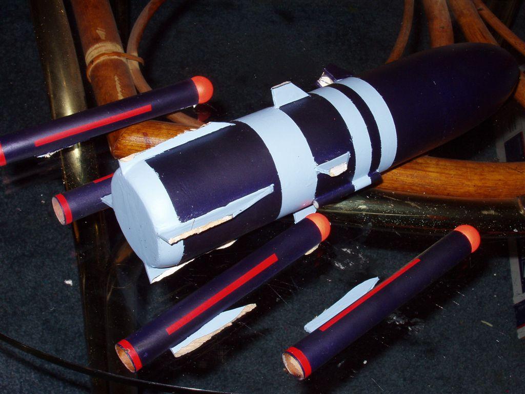
Scratch - Crazy Train {Scratch}
Contributed by Peter Stanley
| Manufacturer: | Scratch |
 Click for Larger Pic |
Crazy Train parts list
- 1 8" BT-80 body tube
- 1 .75" BT-80 coupler
- 1 .25" BT-80 coupler
- 1 2.59" diameter bulkhead
- 1 PNC-80BB nosecone
- 4 5.75" BT-20 body tubes
- 4 .75" BT-20 couplers
- 4 9" Mylar parachutes (originally spec’d with streamers, but later changed)
- 4 BT5-BT20 centering rings (used as engine blocks in 18mm tubes)
- 2 3"x3"x.75" sheets of balsa (for constructing tail cone)
- 1 small sheet of 3/32" (.09375") balsa for 8 small fins and optional mirror mount
- 4 .75 inch wooden balls (can be purchased at a crafts store)
- 1 2" x 3/16" launch lug
- 4 small screw eyes
- 4 medium snap swivels
- 4 12" 100lb strength Kevlar thread
- 4 6" pieces of 1/8" shock cord
- Bulkhead Template (PDF)
- Fin Wrap Template (PDF)
- Forward Fin Template (PDF)
- Rear Fin Template (PDF)
- Tail Cone Template (PDF)
- Mirror Mount Template (PDF)
- Peter Stanley's Word DOC Submission
Crazy Train building instructions
- Cut the tubes to lengths needed.
- Prefinish tubes with 2 sessions of fill n' finish and sanding.
I get good results using bondo putty spreaders. You can cut them to 1/2 wide strips and smear the fill n' finish directly into the spirals. - Cut the fins. Use the provided templates as guides. The grain on the forward fins should follow the leading edge. I did this also on the rear fins, but would now suggest making the grain follow the bottom edge. In this particular configuration I think that perpendicular grain geometry would add more strength. Next, soak the fins in CA glue. First have adequate ventilation, wear gloves, and maybe use a respirator if you have one. Place 2 sheets of wax paper onto a flat glass surface. Put the balsa on top of the wax paper. Squeeze a few drops at a time onto the balsa, and use cut strips of card stock to smear the CA evenly across. Turn the balsa over and repeat. Place two more sheets of wax paper on top. Place another sheet of glass on top of the wax paper. Set something heavy, such as a stack of books on top of that, and let dry for 24 hours. This adds hardness and strength to the balsa.
- Prefinish fins with 2 sessions of fill n' finish and sanding.
- Glue the 3/4 inch balls into the Bt-20 tube couplers. I used a combination of epoxy, superglue, and yellow glue, but whatever works.
 Click for Larger Pic |
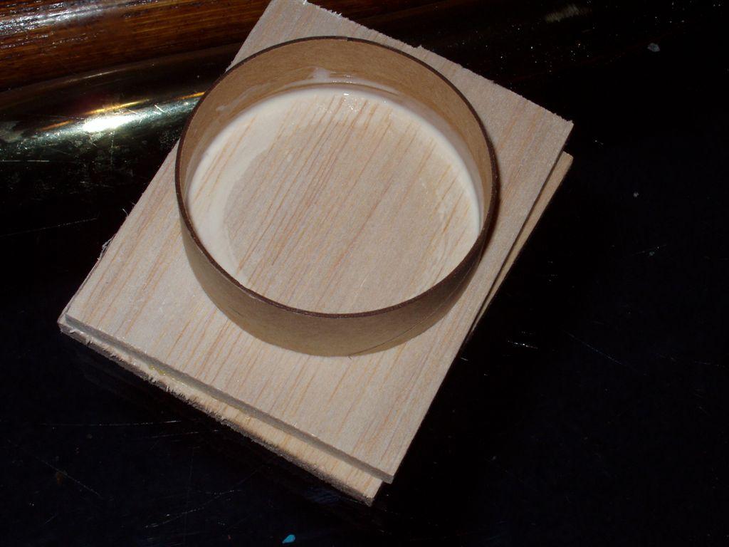
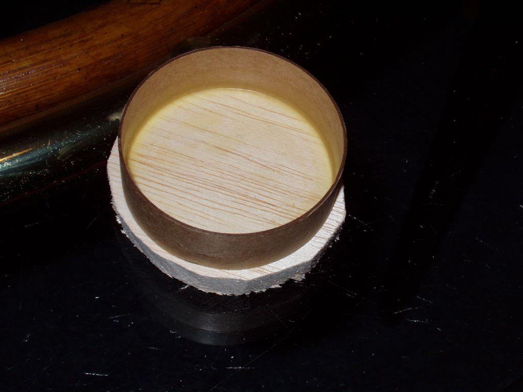
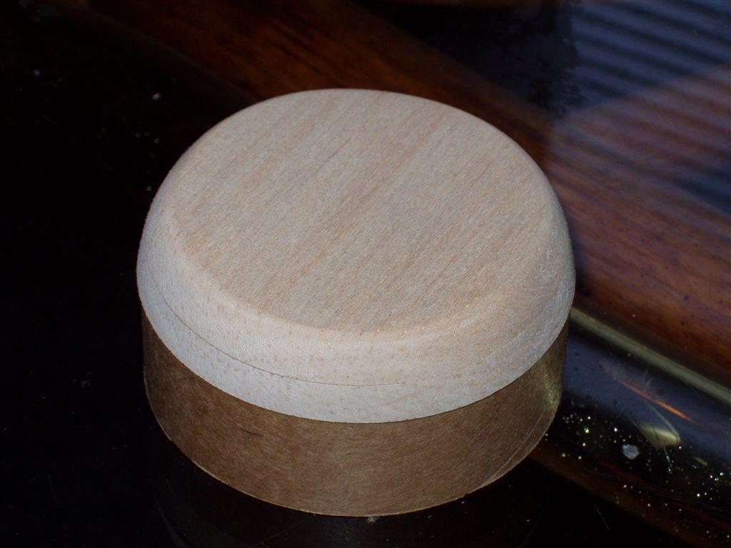
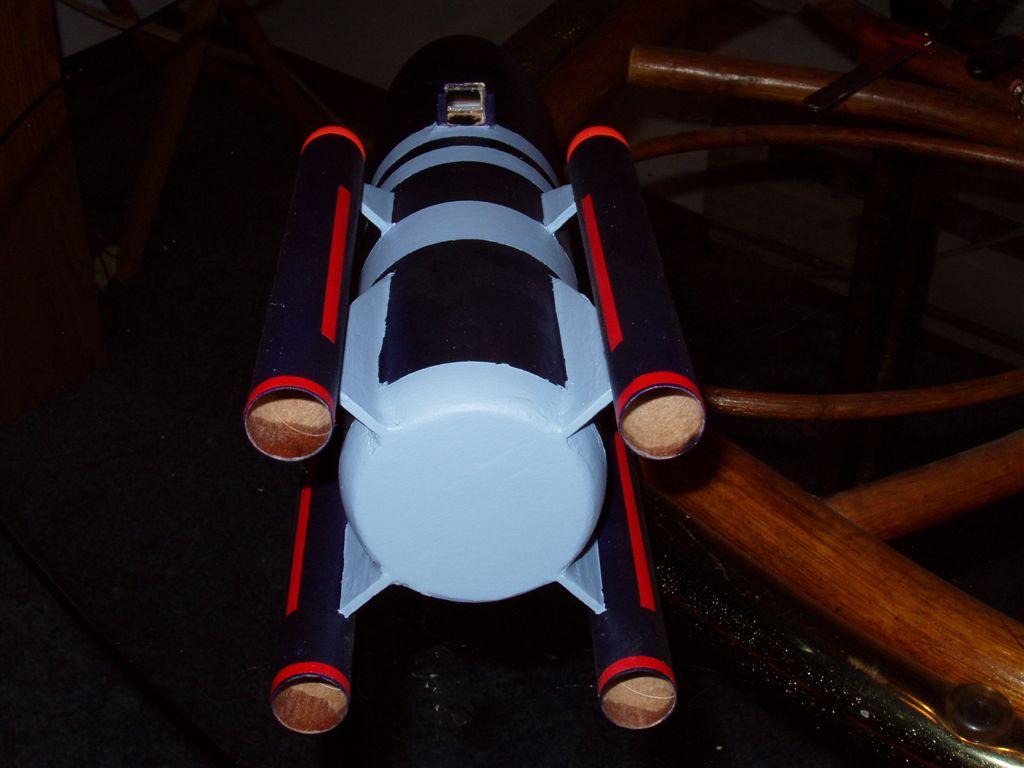
- Glue the two 1/4 inch sheets of balsa together with yellow glue. Clamp or press together with something heavy. When dry, glue the 1/2 inch BT80 coupler to the stack. To shape the tail cone to match the design in Rocksim, I used a method learned from the Apogee Components Making Custom Shape Nose Cones Using Simple Hand Tool CD. Basically you need to hand shape this with sand paper, using the rocksim tail cone template as a guide. You'll need to buy the CD to get the detailed procedure, or figure out a method that works for you. Once the tail cone is finished, glue into the bottom of the main BT80 tube.
<--- Click on Any to Enlarge --->
- Make a straight line down each of the BT-20 tubes. I use aluminum angle for this, but use whatever works for you.
- Use the fin wrapper guide to make four lines on the main BT80 tube. At the middle point where the wrapper edges meet, draw an additional line for the launch lug.
- Tie a piece of Kevlar thread to each BT20 centering ring. Push the thread thru each tube and make sure the centering can slide in. Spread some yellow glue 2.5 inches into a tube. Mark an engine spacing tube, or spent (or not) 18mm Estes motor 1/4 inch from the end. Then and push the centering ring in, leaving the 1/4 inch overhang. Repeat for the other three tubes.
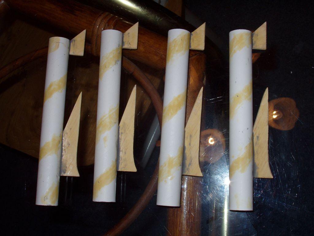
Click for Larger Pic- Glue the forward fin to the end of each nacelle tube. Refer to the 2D image for placement. Glue the rear fin to each nacelle tube, making sure it is in perfect alignment with the forward fin. The back side of the fin should be 1 inch from the bottom of the tube. Refer to the 2D image for placement. I used Apogee's Epoxy Clay for the fin fillets. This will add strength. It's actually Ave's Fixit Compound, but it's the same price whichever place you buy it.
 Click for Larger Pic |
- Drill a 1/16" hole into each 3/4 inch ball on the side that's inside the coupler. Using needle nose pliers, twist a tiny screw eye into each hole, and remove. Put a drip of glue of your choice into each hole and replace screw eye.
- Using razor saw, cut the bottom of the nose cone off leaving 1.25 " of the shoulder left.
- Wick some thin CA into each end of the BT20 nacelle tubes. This will help prevent zippering on the forward ends and reduce possible damage on the rear ends.
- It is easy to get the bottom of the fins out of alignment. A solution I found is to tape a piece of the Kevlar thread in line with a fin line, near the bottom. Pull this over to the opposite side and tape there. Make sure it is straight. Carefully mark on both side of the string to just past where the bottom edge of the fins will meet. I didn't do this for the first fin and had to carve it back off when I realized it wasn't straight.
 Click for Larger Pic |
 Click for Larger Pic |
- Use yellow glue to glue each fin to the body making sure it is as straight as possible. This rocket as it's designed has a high probability of becoming unstable due to the increased chance of asymmetric and off-axis thrust, hence the name 'Crazy Train'. We actually don't want it to live up to its name if we can help it. After each fin is dry, smear more yellow glue into the fin joints. Also, when putting the fins on initially, once the glue sets, use tape to hold it tighter to the body tube. When all fins are dry, use Aves Fixit Compound (epoxy clay) on the fin root joints (If you have some).
 Click for Larger Pic |
 Click for Larger Pic |
 Click for Larger Pic |
- Glue the 3/16" launch lug, with the forward end at 2 1/4" from the forward end of the body tube. If you're using the recommended 2" lug, the bottom edge should be the CP location.
 Click for Larger Pic |
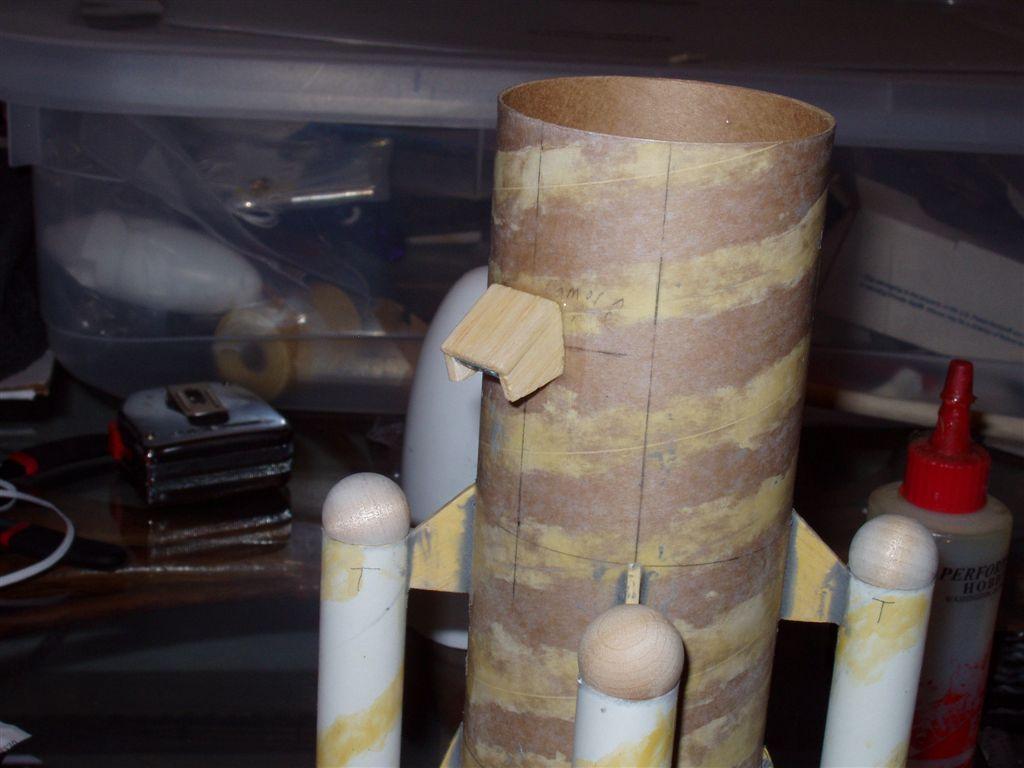
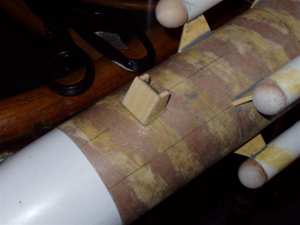
- Optional mirror mount instructions (for wireless Boostervision camera): If you don’t use a camera, at least construct and install the platform in case you want to carry a payload. First, make a platform for the camera to sit on. This keeps it level and at a fixed height. To do this I cut a 1/4" piece of Bt-80 coupler. I made a cardboard bulkhead from a priority mail box. See my article here on how to do this. Print and cut out another bulk template, and mark the exact center of the disk. Stick a needle or something else sharp through it, or whatever works. Align a straight edge to the center and draw a straight line through it. Then glue two pieces of cardboard vertically which will be snug on both sides of the camera. This will keep it from moving left and right. My straight edge tool happened to be the right size to mark off both sides of the center line. You'll need to measure if you don't have something. Basically you need to mark two lines parallel to the center line that you can align and glue a cardboard piece to. This pic shows it better than I'm describing.
 Click for Larger Pic |
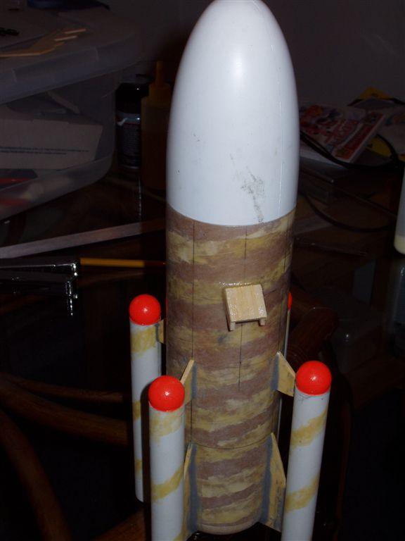
- Make a hole for the camera eye. I first made a vertical center line between two fins opposite the side of the launch lug. I then made a horizontal line between the top of the tube and the point where the top fins attach (approximate 1 5/8" from the top of the tube). At the intersection of those lines, I made a hole with a pin. I then used small drill bits, and hand twisted them, increasing the size of the hole. I eventually had to improvise and twist a knife into in. Later I used a wooden dowel with sand paper. I enlarged it until the camera head would poke through.
- I put the camera in the mount on the platform, and pushed it into the body tube. This is tricky, and you'll want to test this a little before hand, because with the bottom sealed off it's hard to pull it back if you go too far. I had to cut a hole in the platform to pull mine back some. Edge it down gradually, until the camera head is in alignment with the hole, and is level on the platform. Use some yellow glue and glue the platform in.
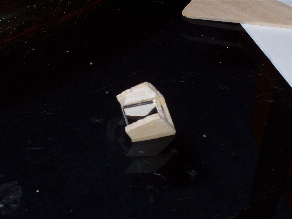
- I used 3/32" balsa to make the mirror housing. The mirror is a 1/2"x1/2" square mirror. I purchased a pack of several 1/2" and 1" mirrors from the craft section of wal-mart for a couple dollars. Most of my time on this build was finding the right angle. I printed fins from rocksim and tried several. When I got something close, I hand adjusted what I had to make it right. I later redesigned the shape in rocksim, and provided the template. I also scanned what I made, so I could reprint templates from those if needed. I used yellow glue to make the housing. I epoxied the mirror into it. I used 5 min. epoxy to attach to the body tube. I applied more 5 min to all joints. Then I used 30 min epoxy and some 3/4 oz fiberglass cloth to cover the housing and reinforce it to the tube. Before you do all this, especially before gluing anything, make sure you test the camera and make sure it looks ok.
 Click for Larger Pic |
 Click for Larger Pic |
 Click for Larger Pic |
 Click for Larger Pic |
 Click for Larger Pic |
- Attach the medium snap swivels to the screw eyes. Tie the 1/8" shock cord to the ends of the Kevlar thread. Use a small snap swivel on the parachutes and attach to the bottom of the medium snap swivels. I originally used 9" nylon chutes, but they will not fit into the tubes. They will, but are extremely tight. The Mylar chutes fit fine.
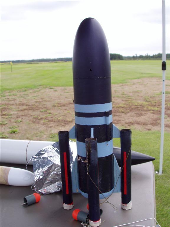
- Before painting, use ¾" fiberglass cloth on the fin joints. I didn’t do this and three of them popped off the first flight. I glassed them afterwards.
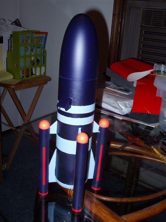
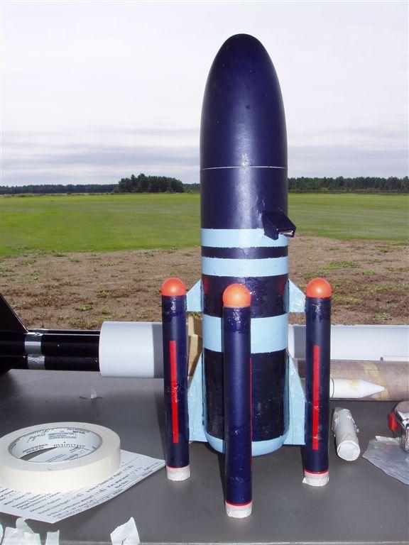
- For finishing I used a combination of spray enamel(main body color), brushed on acrylic (for the orange balls and light blue bands) and vinyl adhesive (for the red stripes).
 Click for Larger Pic |
 Click for Larger Pic |
Flights:
Flight 1:
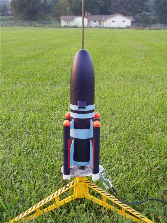
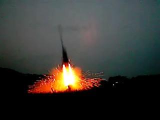
I first flew this on 4 A8-3’s. One of the motors didn’t ignite, and the launch controller wire remained attached. It went about 7 feet and fell over. Even on 3 motors it seemed to have a straight boost. On the first flight I used 4 9" nylon chutes. These chutes were too tight and I think contributed to the damage from the motors trying to eject. Two fins broke off during motor ejection. A third broken upon landing. I glued these back on, and then fiberglassed them with ¾ oz glass. I also changed the chutes to 9" mylar which fit much better.
 Click for Larger Pic |
 Click for Larger Pic |
 Click for Larger Pic |
Flight 2:
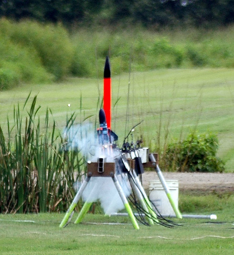
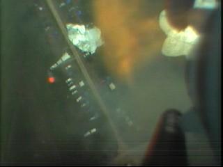
The second flight was on 4 B6-4's. This flight was great, and the rocket suffered no damage. It did arch over slightly, but seemed mostly stable. One of the nosecone/parachutes came off because the shockcord burned through. I lauched this right as it was getting dark, so the onboard video is not that great. The altimeter reported 161 feet.
 Click for Larger Pic (Picture taken by Lilith Briner) |
Flight 3:
The third flight was on 4 C6-3s. This flight was perfect. There was some
spin, but overall it flew in a straight trajectory. Before launch I unwittingly
removed the shockcord segments, leaving just the kevlar thread. This caused a
major zipper on one of the tubes. Also, on another tube the motor block, kevlar
and chute came out. I should have used epoxy on those instead of yellow glue.
The alimeter reported 566 feet.
 Click for Larger Pic |
 Click for Larger Pic |
 Click for Larger Pic |
 Click for Larger Pic |
Flight one is in extremely slow motion, slowed down to about 12% speed.
Flight two was done at dusk, and looks almost like a night launch.
Flight three:
Sponsored Ads


 |
 |