The Launch Pad Standard RIM-67A (Plan)
The Launch Pad - Standard RIM-67A {Plan}
Contributed by Bob Morstadt
| Manufacturer: | The Launch Pad  |
Brief:
This article describes a two-stage (both stages with composite motors) Standard Missile RIM-67A modified from the Plan Pack sold by The Launch Pad.
Construction:
After having difficulty with the second stage ignition system described in the Plan Pack sold by The Launch Pad I proceeded to modify the model to include electronic second-stage ignition. As the model grew in weight I needed to re-build the first stage. Although the first stage looks simple enough, it is a time consuming process using the seamless tube method described in The Launch Pad. It has the advantage of being very light, but is only capable of handling three D motors. Finding a replacement is difficult, because the approx. 3 and ¼ inch diameter is not readily available. I ordered a cardboard tube from England, but it turned out to be too heavy. The most useful tube was made from LOC BT-3.00 tube as shown in Fig. 1 by sectioning two LOC tubes and putting the pieces together. I used through-the-wall fins made from 3/32” aircraft birch plywood that tied into a 29 mm motor mount. The centering rings were also made from birch plywood. The six-foot shock cord is ¾” elastic from Wal-Mart protected by a nomex sleeve threaded through a 10” square nomex blast shield to protect the 44” parachute.
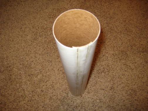
Fig 1. A slightly larger diameter tube constructed from LOC BT-3.00
I kept the first-stage-to-second-stage transition that I made from The Launch Pad Plan-Pack. Fortunately, I found an old cardboard tube from a used roll of tape that had just the right diameter to fit in the first stage airframe. This was epoxied to the bottom of The Launch Pad transition section as shown Fig.2.
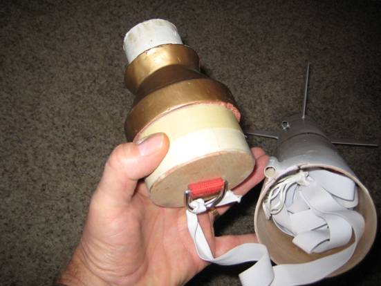
Fig. 2. First-Stage-to-Second-Stage Transition Section,
The second stage uses the The Launch Pad Standard Missile AGM-78 kit with some modification for electronic ignition. I actually made two different second stages each with a different electronic unit. The first model used a G-Wiz LC and the second model used the Perfect Flight MiniTimer3 (MTG3). I figured if one didn’t work, I could immediately try another launch on the same day. It turned out that both electronic units successfully ignited the second stage, however, the first attempt with the MTG3 unit and an Estes E9-4 motor was unstable upon ignition. I decided that the 9 NT average thrust of the BP motor was too low to produce a stable flight and that I needed to change the second model to use a higher thrust model like a composite re-loadable Aerotech F39-9(6). This second choice turned out to be successful.
The second stage is modified with a 24 mm stuffer tube running the length of airframe to the forward parachute compartment. This allows the G-Wiz LC to be housed in a small compartment between the stuffer tube and the main airframe as shown in Fig. 3 and Fig. 4. I made observation portholes by punching holes in the compartment hatch with a paper punch and gluing in pieces of clear plastic from discarded package blister wrap. These portholes line up with the G-Wiz LC indicator/status lights. Two 9-volt batteries are housed in a forward compartment as shown in Fig. 5 next to the parachute compartment shown in Fig. 6. One regular battery is for the G-Wiz LC computer. The other rechargeable N-6PT Sanyo battery has very low internal resistance and is used for the igniter. Follow the G-Wiz LC directions for connecting the correct terminals; otherwise, second stage ignition will occur as soon as the G-Wiz LC is turned on.
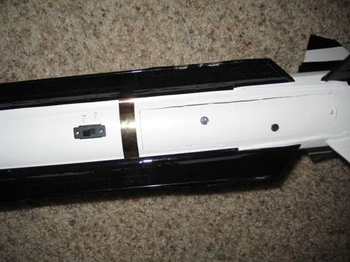
Fig. 3. Electronics Compartment with hatch closed.
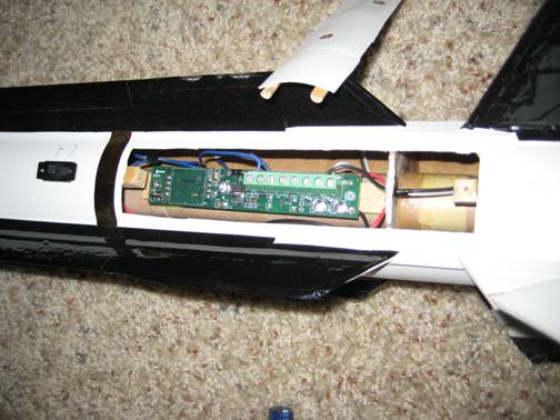
Fig. 4. G-Wiz LC mounted between the stuffer tube and the main airframe.
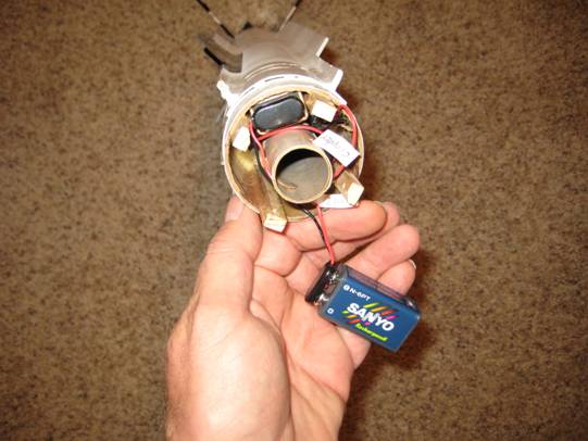
Fig. 5. Forward battery compartment
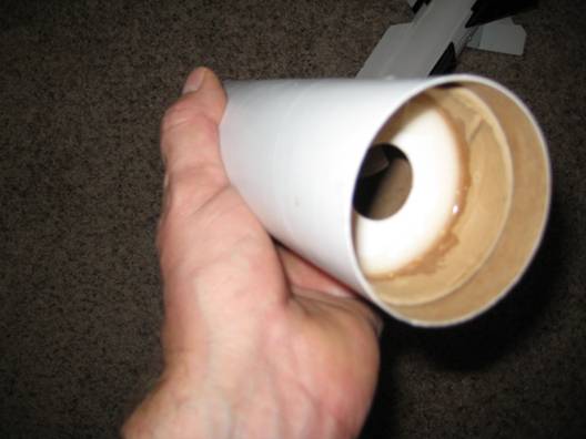
Fig. 6. Parachute compartment slides over the battery compartment and is attached with 4 screws to the main
airframe.
Model airplane birch is cut to length for the struts shown in Fig. 5. These struts hold the batteries in place and also provide the attachment points for the 4 screws that go through the parachute compartment into the struts. The second stage shock ( ½ “ elastic from Wal-Mart) is glued to the inside of the parachute compartment. The completed missile is shown in Fig. 7.
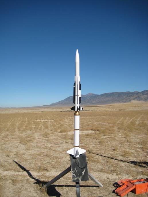
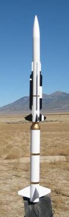
Fig. 7. Standard Missile ready for launch
Flight:
 The first
flight used a G80-4W (now out of production) in the first stage and an Estes E9-4 in the second stage. The second
stage went unstable upon ignition probably due to the low average thrust of the second stage motor. The second
flight used a
The first
flight used a G80-4W (now out of production) in the first stage and an Estes E9-4 in the second stage. The second
stage went unstable upon ignition probably due to the low average thrust of the second stage motor. The second
flight used a
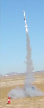
G79-4W in the first stage and a F39-9(6) in the second stage. For the second stage igniter I used a QuickBurst e-match dipped a second time in QuickDip pyrogen. When I built the Aerotech F39 motor I threaded the e-match through the grain slot and then through the nozzle before attaching the end closure. The e-match ignited the second stage instantly for a good flight. Another advantage of using a short burn-time composite motor versus a longer burn-time BP motor was the reduced soot and flame damage in the aft-end of the second stage. There appears to be a accuracy problem with the delay time of the F39-9(6) motor. For this flight the delay time was too long and the second stage suffered a zipper. This can be fixed without much trouble especially with a detachable parachute compartment.
Sponsored Ads
 FREE SHIPPING")


 FREE SHIPPING")


 |
 |