Scratch LUNA III Original Design / Scratch Built
Scratch - LUNA III {Scratch}
Contributed by Chiel Klijn
| Manufacturer: | Scratch |
Note: This is a slightly condensed version of all the information that Chiel has produced for his Level 3 project. Visit the Tripoli Netherlands site (look under Projecten) to read the additional information and enjoy additional pictures.
 General
The Luna III is a high power rocket in its design, weight and performance. The
construction is only of high durable materials. The design is a combination of
own insights into HPR and proven construction techniques. Therefore the Luna
III is meant for achieving my final level.
Different from other models I made is the primary care for strength in the design, not giving way to concessions because of nice looks. The technical and electrical achievements in this rocket are not breathtaking, but widely used and secure. The Luna III must be a rocket which come back alive.
Nosecone
PML prefab nosecone, made of fiberglass. Lower coupler part has been removed
and replaced by a 6 inch coupler tube on a removable bulkhead (for additional
weight adding), to fit in the inner tube (see later). All gluing is done by
epoxy.
The nosecone will be friction fit to the airframe, to prevent premature ejection of the main chute during firing of the drogue charge.
 Body
tube
Body
tube
The body tube exists of 2 tubes, an inner and an outer tube. The outer tube is
PML 7.5'', the inner PML 6''. The tubes are connected to each other by several
aircraft plywood centering rings and the space between them is glued/filled
with polyurethane foam. In this way the tube gets very rigid and so called
''zippers'' belong to the past. From the electronics compartment to the booster
section leads a channel through this space between the tubes for wiring
purposes for possible later features as airstarting.
The outside of the PML outer tube is double covered with 300 and 100 grams fiberglass in epoxy resin.
In the walls of the main chute section, the electronics section and the drogue chute section are holes for air decompression to prevent premature chute deployment and air venting for adequate barometric readings of the on board computers.
In the walls will be reinforced bolts and nuts for installing Blacksky rail
guides.
Main Chute
Rocketman R 18 C chute (same as in Big TinTin project), nomex shock cord
protector, 3 meters rope.
The electronics section
This section contains a double Emmanuel accelerometer with barometric option.
The Emmanuel has separate batteries for the circuit and firing squibs/igniters.
The two systems will work independent of each other, and are not interconnected
by no means. The function will be to fire a charge on apogee in the drogue
chute compartment (based on accelerometer output) and to fire a charge in the
main chute compartment, based on preset barometric readout. The charges will be
single to prevent unnecessary stress of hot gasses, but the igniters in the
charges will be double; each system serves one igniter: the first firing will
ignite the charge. The charges will be housed in a safe eject system, the leads
will go through the bulkhead of the electronics bay in a gas-tight hole.
The housing of the electronics bay will be made of aircraft plywood, fitted in a 6'' coupler tube. The lower bulkhead of the compartment will be glued in place in the coupler, making a permanent gas-tight separation between the drogue chute section and the electronics section, to prevent leaking hot gasses into the electronics bay and disturbing barometric reading, necessary for main chute deployment.
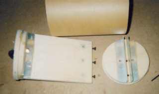
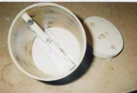
The upper bulkhead will be placed onto the bay by means of bolts and screws. This bulkhead contains the connection to the charge but also has and O'ER to prevent leakage of gasses to the electronics after firing the charge of the main chute section. Whenever leakage might occur, this will only take place after main chute deployment, when further barometric data achievement is for academically use only and not relevant for the flight.
In the hole of the body tube meant for air venting comes the channel for future wiring. So when you look through this hole, you can see the channel lying in the interspace of the two tubes, but more important, though this hole the mini-switches of the electronics are put on before flight and a visual check is possible to see whether they are actual working and ready for take-off.
The electronics section itself is being held in place by two bolts which go right though all walls of the rocket, the coupler and the plywood frame of the bay. All holes will be reinforced by metal tubes.
Drogue chute section
This contains a Rocketman drogue chute on a 5 meter rope. Ejection is backward,
to prevent ''zippers'' and unnecessary stress. Connections of all ropes to the
rocket are by U-bolts.
 Booster
section
Booster
section
The booster section contain the fins, shark-like shaped, but on the tips only
maximal 30 cm away from the frame. Due to the tip the mass will be little, to
prevent fin flutter, which can occur, but is not very likely, because of the
speeds not exceeding 600 km/h. The fins are made of 3mm G10 and attached to the
frame by plywood reinforcements and glassfiber coating. The fins will be
irremovable fixed to the frame, through the wall on the motor mount.
The motor mount is fixed to the body tubes by a series of centering rings, but even more by the full polyurethane filling of the tail segment. In the tail will lead the wiring channel.
 Until now it remains
unclear whether boosters of 54 mm and/or 38 mm motor mounts will join the 75 mm
central motor mount. Reason for this is the unclear possibilities of
airstarting/clustering in launch sites in Europe and the problem of effectively
canting the tubes between CG and CP to prevent problems in igniting air started
clusters. The last is because of the small space left in the body tube to house
all the required motor mounts.
Until now it remains
unclear whether boosters of 54 mm and/or 38 mm motor mounts will join the 75 mm
central motor mount. Reason for this is the unclear possibilities of
airstarting/clustering in launch sites in Europe and the problem of effectively
canting the tubes between CG and CP to prevent problems in igniting air started
clusters. The last is because of the small space left in the body tube to house
all the required motor mounts.
The motor mount has a motor-retainment system; motor ejection however is not used or possible in this rocket.
The tail segment itself is a copy of the nosecone made by multiple layers of glassfiber laminated together. The outer shape does not carry any primary stress of the motor burn during the powered descent phase.
 SUCCESSFUL
LEVEL 3 FLIGHT!
SUCCESSFUL
LEVEL 3 FLIGHT!
March 24, 2001
ALRS 2 Launch - Switzerland
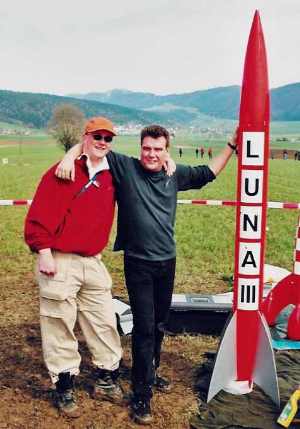
Rocket - Scratch LUNA III
Weight - 66.2 lbs
Motor - Aerotech M1315
Altitude - 6381 ft
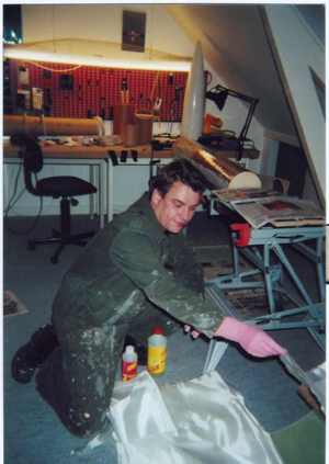
After obtaining my level 2 certification on the medium TinTin flight at ALRS2 I started prepping the Luna III immediately. Strange thing is that I had been working on this rocket so long, I knew every single component without having to check the lists. My friend Renze Hasper helped installing the electronics bay. What I can advice everybody who's planning to fly a big complex rocket is to test parachute deployment at home first. When we were prepping the luna III, we could work just fine because of the mistakes we found earlier. When we placed the luna III on the pad my heart was beating at a real high rate and I felt fine, but also the thrill of this rocket going to be launched after all these solemn hours of working on it.
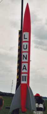
We lifted the rail, and there it stood. I looked great, but from the spectators site, the lettering couldn't be read, that was a pity. I climbed the ladder the activate computers and timers. I opened the hatch, looked, and was amazed: all computers and timers were installed upside down....How could this stupid thing have happened?
 There was no other
thing than to get the rocket off the pad, launching it would mean a crash for
sure. We got the electronics out and with slight wiring difficulties I managed
to turn the electronics. So you see, that when you're really into details,
major construction mistakes can be overseen!
There was no other
thing than to get the rocket off the pad, launching it would mean a crash for
sure. We got the electronics out and with slight wiring difficulties I managed
to turn the electronics. So you see, that when you're really into details,
major construction mistakes can be overseen!
Things seemed to work out fine, however. I wanted to fly this M1315 for sure. This was my lucky day (I got my level 2), and I shouldn't spoil it. Bert's rocket flew, and was a great crowd-pleaser.
I went to the pad as soon as possible because of the wind getting stronger and the clouds getting more dense. I saw a blue spot in the sky, and decided to punch this one with this rocket. I didn't feel good. I had to change major things in this well-designed-and-build-rocket. I didn't feel sure anymore.
We placed the rocket on the pad, I climbed the ladder, armed the
electronics, got back and got a bad feeling. I got up again. I wanted the check
these LEDs blinking the status. And OOH YEAH, I had forgotten the arm the
timer. Now I felt
 REAL bad. Where was
my mind. Thanks God I made 3 independent systems, all would function fine
without this particular timer, but still..
REAL bad. Where was
my mind. Thanks God I made 3 independent systems, all would function fine
without this particular timer, but still..
Sue McMurray attracted all looks on my rocket and couldn't read my handwriting, but what's new (you're a doctor or not).
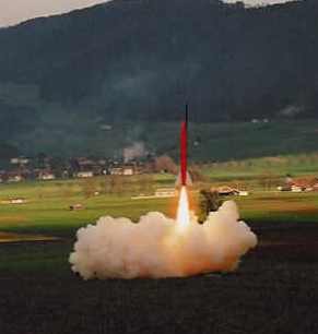
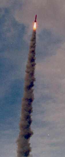
Countdown started. At T-0 the M1315 came alive instantly and pushed the Luna III in the air in a flawless ascent. After 8 seconds or so I lost the tracking. Bert and Frank saw the Luna III first coming down on it's drogues, and saw the parachuting of the main. ''A textbook recovery!'' Bert scanted. I saw the rocket when it came down on its main chute.
Marinus and I took the cars to find the rocket in a perfect shape just over a stream with trees beside! The booster was standing upright!
This was just a great flight!! I let the TAP-members check the rocket, and all was OK. This guy was a fresh owner of a level 3. Whoa!
I decided to stop flying: pushing luck was not to good, I thought. Many people were disappointed because they wanted the BigTinTin to fly. But I felt great, I got 2 levels and the BigTinTin would fly somewhere near in the future, I was in no hurry.
This was just a great day!
Sponsored Ads


 | Intermediate Rocket Kit | Step-by-Step Instructions | Science Education Kits | Great for Teachers, Youth Group Leaders and Birthdays,Blue")
, Launch Pad/ Controller, Glue, Four AA Batteries, and Two Engines")
 |
 |