Essence Aerospace Technologies Triatomic
Essence Aerospace Technologies - Triatomic {Kit}
Contributed by Bob Cox
| Construction Rating: | starstarstarstarstar_border |
| Flight Rating: | starstarstarstar_borderstar_border |
| Overall Rating: | starstarstarstar_borderstar_border |
| Manufacturer: | Essence Aerospace Technologies |
The Triatomic is an interesting design that creates three very different rockets that all share the same upper section. This design served as the inspiration for Virtual Rocket Contest #4.
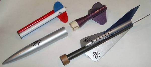
Besides the interchangeable tails, the most unique design innovation on this kit is the “parachute cup” that protects the recovery system. What makes it unique is that it does not get blown out the front of the rocket like most piston systems. Instead, the cup is yanked out the rear of the upper body by the momentum of the lower section ejecting backward. This turns out to be the most troublesome part of the design, as will be seen below.
CONSTRUCTION:
Once again, Chan Stevens has submitted a review ahead of me. Rather than repeat the parts list, I will refer you to his thorough review.
Like Chan, I was surprised at how much stuff fit in such a small shipping box. The longest tube, which forms the lower fuselage of the Futuristic version, was a bit squashed and had a slight crease, but that was not a show-stopper.
My first reaction after taking all the parts out of the box was “Wow! There’s a lot of wood in here. I’m going to be busy sanding for a while.” The transition and the nose cone both had a fairly rough surface and the balsa was quite light and soft.>
Instructions: The instructions consisted of 12 pages of regular instructions, heavily illustrated with color photos. The instructions are very detailed, and include “Durability Hints” detailing what surface should be coated with CA or epoxy to prolong the life of the rocket. In addition, based on flight experiences with the prototypes, two supplemental pages were included. I had a bit of confusion with some of the supplemental directions, but Nick at EAT was very responsive to e-mail and I was soon on my way again.
Fins: The first step is cutting all the fins. The basswood is nice and hard, so the cutting takes a while and my fingers started getting sore, but the resulting fins are very nice. Also, they are not all needed at the same time, so the cutting can be spread over several sessions.
Upper Body: The next main section is building the upper body. Here is where I would recommend a few changes to the instructions:
- Step 1B recommends tying the elastic shock cord to the Kevlar shock cord anchor. I think this should be moved to Step E so the elastic is not in the way when gluing the nose cone and fitting the parachute cup.
- If Step 1D (gluing on the nose cone) was moved to be the final step, after Step 1H, the parachute cup fitting process will be much easier.
- Step 1D has a Durability Hint that suggests soaking the bottom 1” of the upper body tube with CA and then sanding with 400 grit paper. This should not be just a suggestion. The entire tube, except for the top 1”, should be treated with CA and sanded VERY smooth before gluing the nose cone in place.
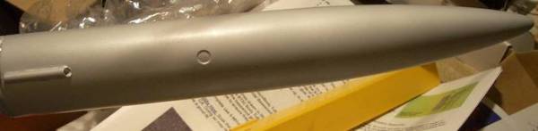
- VERY IMPORTANT: The parachute cup gets a hole drilled in its side during step 1E. This hole is supposed to release the vacuum in the upper body that forms when the cup is jerked backward. Unfortunately, the cup needs to move more than an inch before this vent hole is uncovered, and it builds up a good strong vacuum in that time. A ¼” vent hole in the side of the upper body tube, right at the base of the nose cone, will relieve the vacuum before it ever has a chance to build up. I put mine in line with the launch lug so it wouldn’t interfere with the decals on the other side.
- EVEN MORE IMPORTANT: In Step 1H the outside of the parachute cup get coated with CA, and then sanded down to fit smoothly inside the upper body. I spent a couple hours on this step trying to get it to extract smoothly (this was before I put the vent hole in the body). I strongly recommend peeling at least one layer off the outside of the cup before applying the CA. If the cup does not come out smoothly, bad things are gonna happen in flight.
After the upper body is complete, each of the lower bodies is assembled.
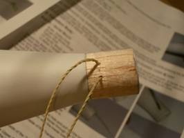
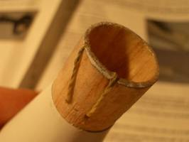
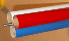
Transition Body: The Transition body is fairly straight-forward. The only tricky part is attaching the Kevlar anchor loop. The original directions used a single Kevlar string, but the supplemental instructions call for the Kevlar to be doubled into a loop. The supplemental instructions were not very clear about how to anchor the loop, so here’s how I did it:
 First, I
drilled two tiny holes through the rear shoulder of the transition.
First, I
drilled two tiny holes through the rear shoulder of the transition.
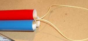
 Then I
passed the ends of the Kevlar through the holes and tied them together.
Then I
passed the ends of the Kevlar through the holes and tied them together.
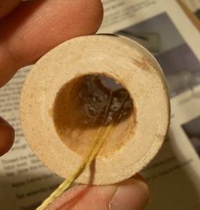
 Next, I
wrapped the strings around the back end of the transition and passed them out
the front end.
Next, I
wrapped the strings around the back end of the transition and passed them out
the front end.
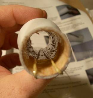 Then I
coated the inside of the transition and the cords with 5.minute epoxy to
protect them from the heat of the ejection charge.
Then I
coated the inside of the transition and the cords with 5.minute epoxy to
protect them from the heat of the ejection charge.
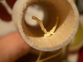
 This is what
it looks like from the front.
This is what
it looks like from the front.
After that, the rest of the build was simple: attach the body tube to the transition, and glue the fins to the body tube. I swapped steps 2B and 2C, attaching the fins first so that the transition did not get in the way of my Estes fin alignment guide. I used 5-minute epoxy for the attachment and the fillets.
The lower body is the same diameter as the engine, so there is no room for an engine hook. I moved the fins forward ¼” to provide a surface to tape the engine onto for motor retention.
Cluster Body :
The cluster body consists of three pieces of BT-20 in a triangular arrangement. A threaded rod is anchored between the tubes on the rear end to provide for engine retention. The Kevlar anchor loop is attached out the front. A black fiber centering ring is attached to the front to mate with the upper section.
Finally, the fins are glued in the grooves between the tubes. I beveled the root edges of the fins so that they would have more surface area in contact with the tubes.
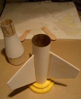
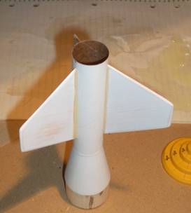
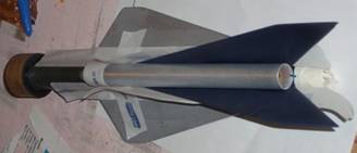
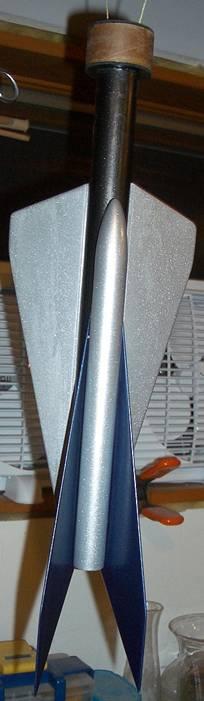
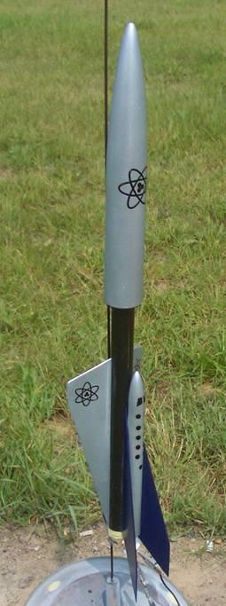
Futuristic Body : This is the most complex and the most interesting-looking of the three bodies.
First a coupler is built to mate with the upper body section. The directions call for using a three-fold shock cord mount to attach the Kevlar anchor loop. The force on this rear-ejection design may be much larger than a normal front-blow design, so I wanted to do something a bit beefier. Before I glued the coupler together, I poked two holes in the body tube 180 degrees apart and passed the ends of the Kevlar string through them. Then I knotted them together and finished constructing the coupler. I covered all the thread hidden in the coupler with epoxy to keep the knot from slipping and to spread the force over a larger area.
 Attaching
the fins turned out to be quite an adventure. The ventral fins are
“backwards” and taper to a narrow point at the rear, so my Estes fin
alignment guide did not have enough fin area to make good contact. If I
had changed the build order and attached the coupler last, I could have aligned
the guide from the other direction. As it was, I had to keep nudging the
fins while the epoxy hardened to keep them in line with the fin alignment
template.
Attaching
the fins turned out to be quite an adventure. The ventral fins are
“backwards” and taper to a narrow point at the rear, so my Estes fin
alignment guide did not have enough fin area to make good contact. If I
had changed the build order and attached the coupler last, I could have aligned
the guide from the other direction. As it was, I had to keep nudging the
fins while the epoxy hardened to keep them in line with the fin alignment
template.
As I did on the Transition body, I mounted the fins ¼” forward to allow for masking tape motor retention.
I also used a small straight pin to poke holes in the body tube every
¼” so the epoxy would soak through the holes and form
“rivets” for added strength.
I used 5-minute epoxy to make the fillets. To make them nice and even, I apply masking tape on both sides of each glue joint, and then apply the epoxy. A Popsicle stick or a gloved finger dipped in rubbing alcohol was used to smooth the fillets. The tape was removed when the epoxy was well gelled but not fully hardened.
Unlike the ventral fins, the dorsal fins have a more conventional swept-back shape. What makes them trickier to align is the dorsal body tube that must be placed between them. Once again I could not use my fin alignment guide to hold the fins in place, so I had to nudge the parts back into proper alignment several times while the epoxy was setting.
Recovery System: The parachute provided was a RocketHead Rockets pre-built 21” mylar chute. I really like the quality and convenience of the RocketHead chutes. It almost brought a tear to my eye to have to cut the shroud lines to make them shorter so they could be reliably extracted from the parachute cup.
 Finishing:
Normally I use Elmer’s Fill ‘n’ Finish on balsa surfaces. The nose cone and transition on this kit were fairly porous and I wanted a glassy smooth finish, so I decided to try sanding sealer for the first time. I used AeroGloss brand from Hobby Lobby. It gives off some wicked fumes when it’s wet, but it does give a very nice surface after being sanded. I used two coats with sanding between, then two coats of Rustoleum Painters Choice primer with sanding between.
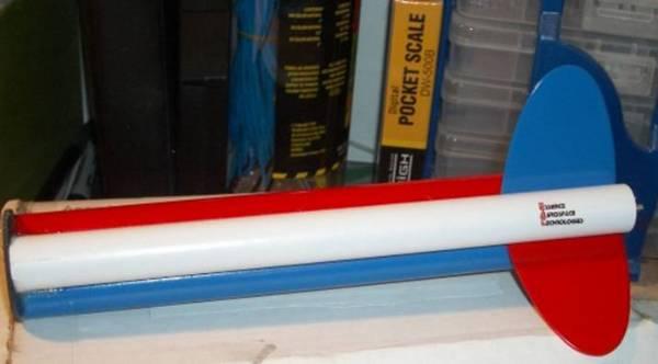
All the paint I used is by Rustoleum. The upper body is painted with Brilliant Metallic Silver. The Transition body is Deep Purple Metallic. For the Cluster body I used three colors of Rustoleum Painters Choice: White, Apple Red, and Brilliant Blue. On the Futuristic body, the main tube is Black Night Metallic, the upper body and the ventral fins are Brilliant Silver Metallic, and the dorsal fins are Cobalt Blue Metallic. I like the contrasting color on the ventral fins because it emphasizes the asymmetry of the two fin sets, plus the decals show up better on the light colored background.
A good-looking set of water-slide decals was provided with the kit. Unfortunately, they were not very strong, and I managed to ruin four of them. Fortunately, none of the damaged decals were the ones I cared about the most.
After the decals were dry, I coated all the decals and all the metallic paints with two coats of Future floor polish. This stuff really brings out the sparkle and shine on metallic paint.
Overall, I’m really pleased with the appearance.
Construction Rating: 4 out of 5
FLIGHT/RECOVERY
Recovery System:
One of the most innovative features of this kit is the parachute cup that protects the recovery system and completely eliminates the need for wadding.
Most of the recovery system stays with the upper body. It consists of a short Kevlar cord attached to the nose cone, a 2-foot piece of 3/8” elastic cord, a metal anchor ring, and a 21” Mylar parachute. Each of the lower rocket bodies has a Kevlar loop that attaches to the parachute cup.
Pre-Flight Preparation:
The preparation for all three variants of this kit starts out the same, and is quite different from most other kits. The Kevlar loop from the lower body is inserted through a hole in the bottom of the parachute cup, passed through a metal washer, and looped through the eye of a snap swivel. The snap swivel is then clipped to a ring on the end of the elastic cord.
This procedure is kind of slow to put together and slow to take apart after a flight. It would probably be faster if the snap swivel was permanently attached to the elastic cord and then snapped onto the Kevlar before each flight. I’m not sure if that would concentrate too much stress on one spot of the Kevlar, or if the snap might open up.
Next, the parachute is folded and inserted into the cup, along with the elastic cord. Then the loaded cup is inserted into the upper rocket body until it touches the nose cone. Finally, the lower body is plugged into the upper body.
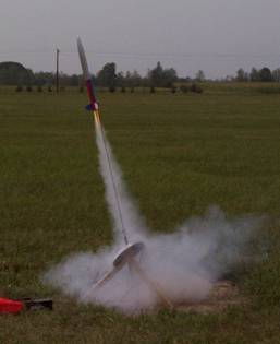
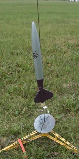 Transition Flight:
Here is the list of recommended motor for the Transition version. The transition is the lowest-drag version, and it really soars on an E9 engine.
|
|
RockSim |
| B6-2 |
195 ft |
| C6-5 |
590 ft |
| C11-5 |
565 ft |
| D12-7 |
1275 ft |
| E9-8 |
2465 ft> |
I wanted to get mine back so I could fly all three configurations, so I flew the maiden flight on a C11-5. There is no engine hook, so I wrapped two turns of masking tape around the bottom 1/4 inch of body and the exposed portion of the motor.
The first flight was beautiful. Fast straight takeoff, perfect ejection at apogee, perfect chute deployment. Drifted about 800 feet, just missing a row of tall pines, and landed gently in tall grass. No damage, no scorching – not even on the bottom of the parachute cup. Excellent!
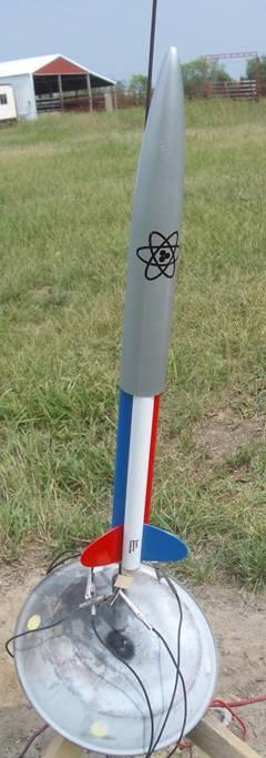
Cluster Flight:
Here is the list of recommended motor for the Cluster version.
| Engine |
RockSim |
|
3x 1/2A6-2 |
73 ft |
|
3x A8-3 |
270 ft |
|
3x B6-6 |
790 ft |
|
3x C6-7 |
1735 ft> |
After seeing how far the previous flight drifted, I was a bit leery of using the B6’s. Instead I used three A8-3’s, since I had plenty of them left from the Estes Blastoff Flight Pack.
The engines are retained by a nut on a
 piece of threaded rod located between the
engines. This is a very slick retention system that is easy to load and
unload and holds the motors securely.
piece of threaded rod located between the
engines. This is a very slick retention system that is easy to load and
unload and holds the motors securely.
This was my first-ever cluster attempt. Zak Orion is the cluster king in the MARS club, and he let me use his cluster-whip, for which I am thankful. The launch was great -- all 3 engines lit and the boost was nice and fast.
Ejection occurred just past apogee. The lower body came out correctly but the parachute cup did not pull out completely, so the parachute was trapped inside the upper body. It landed hard on grass/mud, kinking the booster tube near coupler. It will need some repairs before it flies again.
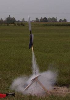
Futuristic Flight:
Here is the list of recommended motor list for the Cluster version:
| Engine |
RockSim |
| B6-2 |
115 ft |
| C6-3 |
355 ft |
| C11-3 |
350 ft |
| D12-5 |
840 ft |
| E9-6 |
1750 ft |
We were all out of C11-3’s, so I used a C6-3 in the 18mm adapter.
Like the
 Transition version, the Futuristic has no engine
hook, so once again I wrapped masking tape around the rear of the rocket and
the exposed part of the engine adapter.
Transition version, the Futuristic has no engine
hook, so once again I wrapped masking tape around the rear of the rocket and
the exposed part of the engine adapter.
After the bad experience on the previous flight, I wiped the parachute cup and the inside of the upper body very thoroughly before loading the cup.
The boost was pretty, but not very high. Ejection occurred just past apogee. Once again, the chute cup bound in the upper body, so once again no parachute deployed, and it landed hard in a soybean field. An epoxy fillet on one dorsal fin cracked, but it is still flyable.
- Flight Rating: 5 out of 5
- Recovery Rating: 2 out of 5
OVERALL:
This was a very interesting kit to build and to fly. The styling on the Futuristic is very sleek and unlike any other kit, and the Transition is elegant in its simplicity. The variety of engine options allow for a lot of flexibility to adapt to different wind conditions. For the money, this is a whole lot of rocket. If the parachute cup was more reliable, this could have scored a ‘5’.
PROS:
- Nice looking
- Versatile
- Innovative
- Detailed instructions
- Great customer support
CONS:
- Parachute cup jams during flight
- Decals are a bit fragile
Overall Rating: 3 out of 5
Other Reviews
- Essence Aerospace Technologies Triatomic By Doug Szczepanski
( Contributed - by Doug Szczepanski - 07/09/06) Brief: Parachute cup modification. Modifications: I had already epoxied the plywood bulkhead in place when I read of some of the problems with the parachute cup releasing from the upper rocket. Take a Rotozip tool (or use a similar cutting method) with a wood cutting bit and cut a hole in the bulkhead leaving ~1/4" lip. ...
- Essence Aerospace Technologies Triatomic By Bob Cox
Brief: EAT's latest offering is an amazing 3 in one rocket. Look! Up in the sky! It's a cluster! No, it's a 24mm transition rocket! No, it's a sleek futuristic space plane! You can fly 3 completely different configurations on the field the same day using this very innovative design concept. Construction: I was initially hesitant to pop for the $36 (includes shipping) kit, but ...
 |
 |
Flights
Sponsored Ads


")


")


|
|