Scratch Cascade Original Design / Scratch Built
Scratch - Cascade {Scratch}
Contributed by Geof Givens
| Manufacturer: | Scratch |
Brief:
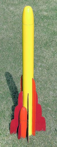
Cascade is a breakaway parallel-staged rocket standing 33.75" tall,
2.6" diameter, and weighing 17.5oz. Two breakaway semi-cylindrical
boosters are intended for 18mm B6-0 or C6-0 motors with a central 24mm motor in
the main tube, originally intended for a E9-4. If everything goes according to
plan, the launch should feature 3-way cluster ignition with two boosters
dropping off the main rocket quickly and returning by parachute while the main
rocket powers into the stratosphere. With the degree of complexity and the
overall weight of the build, another very likely outcome is substantial
re-kitting.
I never would have attempted this without the EMRR 2006 Challenge pushing me. Design and construction were quite challenging. The name "Cascade" stems from the repeated elliptical motifs in all the fins and noses, which evoke images of waterfalls. Being somewhat of a pessimist about this project, I think it may also end up referring to the volume of shredded parts cascading down all over the launch vicinity. We'll see.
Construction:
The boosters began as a single BT-70 tube section and NC70 nose cone. The tube
was halved lengthwise. The nose cone was halved vertically. I have not found a
satisfactory way to do this with my tools (no bandsaw) and I welcome
suggestions. A kitchen knife worked better than my jigsaw.
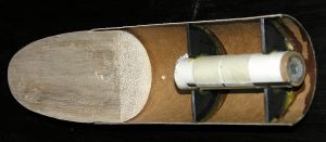 Two CRs were
halved and the inner holes expanded and shifted to accept BT-20 engine mounts.
The engine tubes were aligned to be flush with the flat edge of the half-tube.
The open sides of the half-tubes were closed with flat panels of 1/16"
balsa. The flat side of the nose was backed with a matching piece of 1/4"
balsa. Note that this causes the flat side of the booster to have a ledge where
the nose joins the body. This is intentional to aid mounting on the main
rocket.
Two CRs were
halved and the inner holes expanded and shifted to accept BT-20 engine mounts.
The engine tubes were aligned to be flush with the flat edge of the half-tube.
The open sides of the half-tubes were closed with flat panels of 1/16"
balsa. The flat side of the nose was backed with a matching piece of 1/4"
balsa. Note that this causes the flat side of the booster to have a ledge where
the nose joins the body. This is intentional to aid mounting on the main
rocket.
The profile of the booster was traced onto a template, which was used to construct a flat mounting panel which would be attached to the main rocket. The nose portion of the mounting panel was 1/16" balsa and the body portion was 1/4" balsa. Note that these thicknesses compensate for the ledge on the booster.
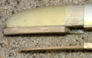
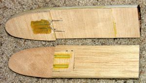 Forward
mounting pins were constructed from paperclips. A trough was cut in the booster
nose cone with the paper clips epoxied in. A square of 1/16" balsa was cut
to permit two inch-long lugs to be glued in flush with one side and then this
subassembly was glued into a trough cut in the top of the 1/4" mounting
panel portion. When the booster nose blows, this will detach the top of the
booster from the main rocket.
Forward
mounting pins were constructed from paperclips. A trough was cut in the booster
nose cone with the paper clips epoxied in. A square of 1/16" balsa was cut
to permit two inch-long lugs to be glued in flush with one side and then this
subassembly was glued into a trough cut in the top of the 1/4" mounting
panel portion. When the booster nose blows, this will detach the top of the
booster from the main rocket.
The bottoms of the boosters have small brackets which clip below the body tube, thus transferring the upward thrust of the booster to the main body. These clips do not secure the boosters to the main rocket in any way, except they are slanted upwards and inwards to prevent the tails of the boosters from wobbling during thrust. After the booster nose detaches, this leaves the rear of the booster free to simply fall away. [Note: none of the photos shows these clips, which were installed at the end.]
 This booster
setup and attachment method was designed to work separately for each booster.
If a booster failed to ignite, this design keeps it attached to the main rocket
for the entire flight.
This booster
setup and attachment method was designed to work separately for each booster.
If a booster failed to ignite, this design keeps it attached to the main rocket
for the entire flight.
The center rocket was almost an afterthought. It has a 2.6 inch heavy duty BT-80 tube, elliptical nose cone, and a standard engine mount setup, with Kevlar® tied to the top CR. It turned out to be a major mistake to use the heavy duty BT-80 instead of the standard, because the rocket turned out too heavy for its intended motor combination. The next step was to glue the booster mounting panels to the main body.
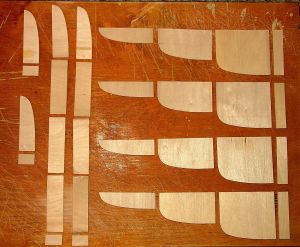 Nearly 50 pieces
of 3/32" basswood were used to build the fins. Each fin was made from 2,
4, or 5 portions glued together to ensure optimal grain orientation. The small
fins are centered on each booster. The long strakes attach 90 degrees around
from these on the main body centered between booster mounting panel edges. The
main fins required more care. These attach to the main body so that they are
perpendicular to the main body tube and just touch the booster mounting panels
at about a 45 degree angle. These fins are filleted to the body tube on the
"outside" and the top portion of the "inside", where the
"inside" is the fin side closest to the booster mount. This created a
small cavity under the mounting panel and is enclosed by the main fin with an
open curving gap at the top where the booster nose curves away. There is also a
triangular gap at the tail. I scrapped plans to fill these entrances to the
cavity due to weight considerations.
Nearly 50 pieces
of 3/32" basswood were used to build the fins. Each fin was made from 2,
4, or 5 portions glued together to ensure optimal grain orientation. The small
fins are centered on each booster. The long strakes attach 90 degrees around
from these on the main body centered between booster mounting panel edges. The
main fins required more care. These attach to the main body so that they are
perpendicular to the main body tube and just touch the booster mounting panels
at about a 45 degree angle. These fins are filleted to the body tube on the
"outside" and the top portion of the "inside", where the
"inside" is the fin side closest to the booster mount. This created a
small cavity under the mounting panel and is enclosed by the main fin with an
open curving gap at the top where the booster nose curves away. There is also a
triangular gap at the tail. I scrapped plans to fill these entrances to the
cavity due to weight considerations.
Finishing:
After a depressing amount of filling and sanding, it was time to paint. Having
rushed and screwed up my last paint job, I was determined to take my time with
this one, and the results were excellent. The red and yellow are Rustoleum and
the orange is Duplicolor Ceramic Engine Enamel. The orange paint looks great,
but it does require 1 week of drying time. Light coats of Krylon clear went
over the top.
Flight:
The final rocket was pretty heavy with a lot of tail weight. I figured I ought
to give it a swing test. The results suggested that I really ought to see my
neurologist about dizzy spells, but were inconclusive about the rocket. I
couldn't bear to add nose weight to this beast, so I decided to take my
chances.
I opted to use rail buttons so I could take full advantage of a 6-foot rail for safety. I also pulled out my 36-inch competition mylar chute. This was overkill, but might give a softer landing for those basswood fins if the chute doesn't shred on ejection. I had some 14-inch chutes laying around, so I used these for the booster pods without thinking about it too much.
A E9-4 has a burn time of 2.8 seconds; the B6-0 and C6-0 have burn times of 0.8 and 1.6 seconds, respectively. The spirit of the EMRR Challenge is to have the boosters fall away quickly, so I opted for the two B6-0s plus the E9-4, saving the more powerful boosters for another day. I have no idea how high either motor combination would put the rocket, but I knew the velocity at the end of the rail would be marginal at best.
First launch was at Mile High Mayhem. The rocket struggled off the rail with the boosters popping off at the neck-stretching altitude of about 15 feet. They landed undamaged before the chutes had time to fully deploy. The good news was that the B6-0 burn through did provide plenty of forward pressure to pop the pod noses, thus the parallel staging worked about as well as one could hope.
The main rocket clawed its way upward on an arching trajectory, underpowered.
Recovery:
The delay was too long for the rocket's meager velocity, so the ejection was
considerably late. This caused the chute to shred on ejection, providing
streamer recovery for the 1 pound main rocket. Remarkably, only one fin broke
on landing, and it was a clean break which can be easily repaired. The chute
shred also caused a near-zipper. I pushed the tube back into shape.
Summary:
Since I built this for the 2006 EMRR Challenge, I'll repair and try launching
again. However, it is clear that I will need to abandon the idea of a long
burn-time differential between the pods and main rocket, opting instead for a
main engine with greater initial thrust, like a E30 or F21.
Looking back on this project, a parallel-staged rocket with dropaway booster pods is a pretty ambitious project that I wouldn't recommend to beginners. It does open up a new corner of the hobby though for people looking for a serious challenge.
Sponsored Ads


 |
 |