Scratch SP2050 Freightliner Space Truck Original Design / Scratch Built
Scratch - SP2050 Freightliner Space Truck {Scratch}
Contributed by Drake "Doc" Damerau
| Manufacturer: | Scratch |
Click on Pics to Enlarge
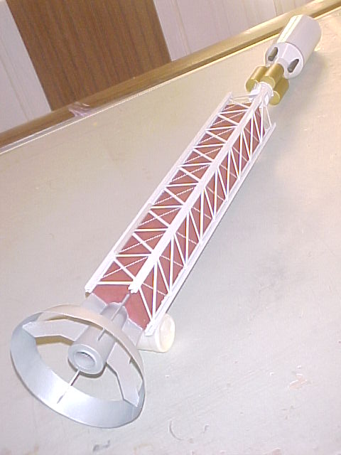
This is the model SP2050 Freightliner Space Truck
To me, this looked like a series of cargo containers inside a truss framework.
The cargo containers are slid into the framework. Once they are in place, the inertial dampeners and shields are activated. Life support can be activated if there is live cargo, such as livestock or if a prisoner transport module is loaded.
The ship is 1,000 feet long and the GVW is less than 300 tons. It is an intrasolar vehicle, so warp capability it not needed. Having a 20,000 horsepower impulse engine made by Detroit Diesel and General Motors maneuvering thrusters, this is the fastest cargo ship in the FedEx fleet.
The forward section contains engineering and crew quarters. The aft section contains the impulse engine. It is designed to ferry cargo from the docks in low earth orbit, to the docks at Mars and Europa.
Cargo area
- 1 - Balsa Sheet 1/16" x 4" x 36"
- 4 - dowels - 1/8" x 36"
- 1 - bag of 250 count 5/64" x 2 5/8" "mini dowels" by Forster
- 8 - 1/4 x 1/8 sticks
- Kevlar String
- 1 - BT50 x 18"
- 3 - BT50 - BT60 Adaptor Cards
Cab
- 2 - BT50 - BT60 rings
- 2 - BT50 - BT80 rings
- 1 - 5" BT50
- 1 - 4.5" BT80
- 1 - 1 1/2" BT60
- 1 - Paper shroud
- 1 - bt BTXx bulkhead
- 1 - BTx bulkhead
Tanks
- 4 - 2" BT50
- 8 discs from BT50 centering rings
- 1 - 4 1/2" length of BT80
- Tank/Cargo adaptor
- 3 - BT50 to BT55 rings
- 1 - 1" section of BT50
- 1 - BT50 to BT20 adaptor tube
- 1 - 1" section of BT20 tube
- 4 - BT20 to BT5 adaptor rings
- 1 - 5" section of BT5 tube
- 3 - BT50 to BT20 rings
- 1 - 1" BT20 tube
- 1 - BT20 to 1.250 card ring
- 1 - 5" x 1/2" wooden dowel
Aft End
- 1 - BT50 3"
- 1 - BT50 to BT60 ring
- 1 - Coupler
- 1 - Paper Shroud
- Fin stock
- 5" x 6" x 1" shroud.
- Fin Template
Misc
- 2 - 18" chutes
- Shock cords
Truss and cargo box
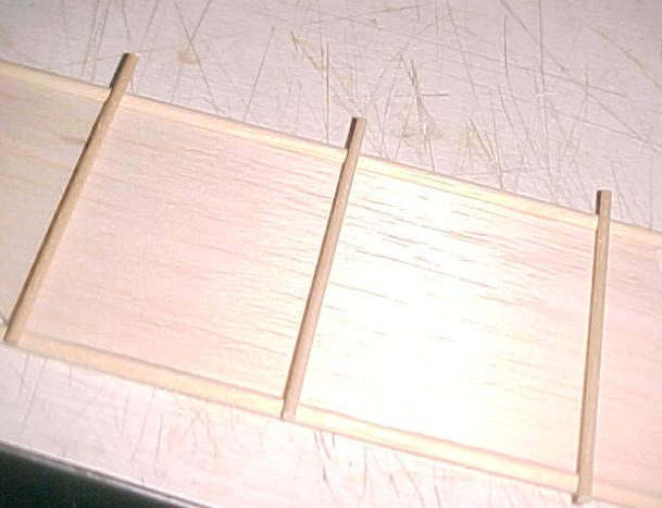
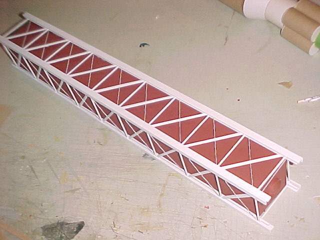
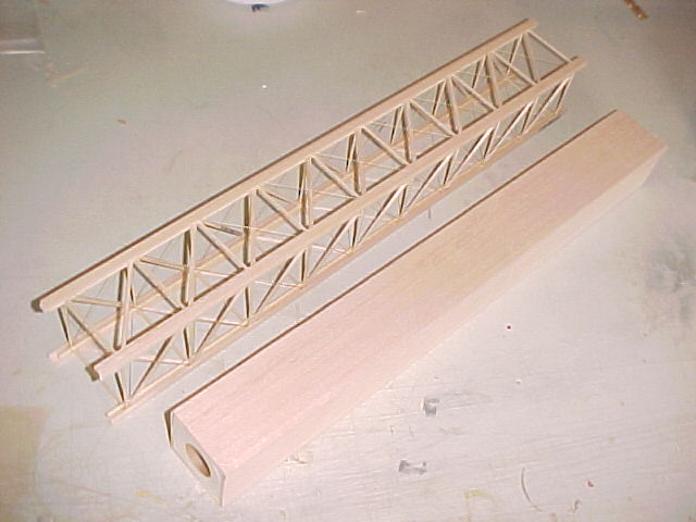
Cut the balsa sheets into 4 sheets 18" x 1 7/8" pieces. This will provide the spacing need to use the small dowels at a 45 angle. (I made the mistake of making them too wide and not being able to use them.)
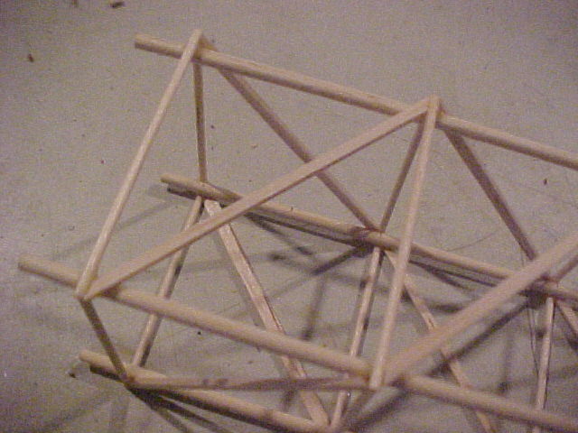
To make the trusses, cut the 1/8" dowels into four 19". Use the balsa sheets as guides for lining up the large dowels. Glue the mini dowels to the 1/8" dowels in 1 7/8" intervals, being careful not to glue anything to the balsa sheet. See pictures 1 & 2 for this. Make two of these trusses. Do not glue the 45 angle dowels yet.
 |
 |
 |
| Figure 1 | Figure 2 | Figure 3 |
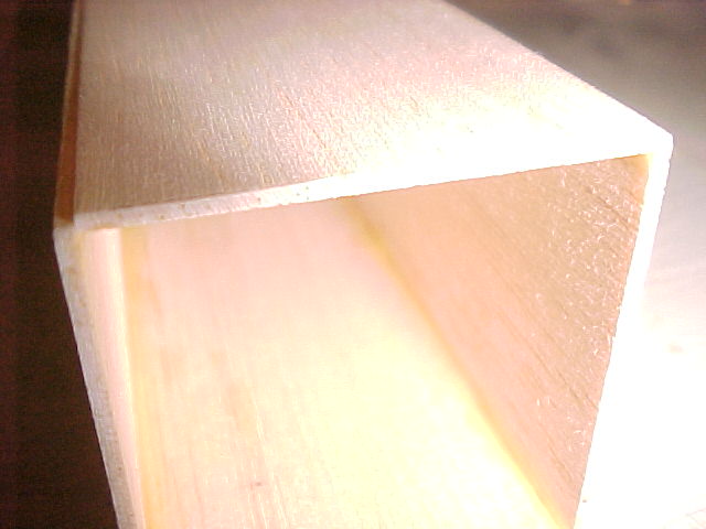
Make the cargo box by gluing the 4 sheets of balsa together. See picture 3 to see the arrangement of the sheets. This arrangement will help the positioning of it in the truss work. Strong fillets will be needed on the ID of the box for strength.
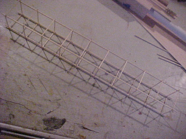
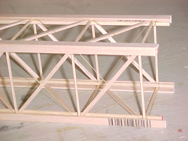
Now back to building the truss, trim the small dowels so that they are flush with the large dowel. Using the balsa box as a spacer again, finish the truss. Once this is dry, start gluing the 45 angle dowels on. It should now look like figure 4.
Using Kevlar string, wrap the truss in the opposite direction to form a series "X's" over the truss. If I had this project to start over again, I would use the Kevlar string for all the 45 angle cross bracing.
 |
 |
 |
| Figure 4 | Figure 5 | Figure 6 |
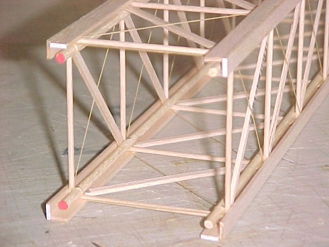
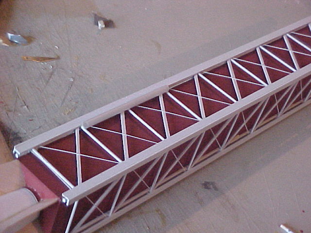
Finish the truss work by gluing on the 1/8" x 1/4" balsa onto the corners. Make sure none of the small dowels are protruding over the large dowels. I did this with toenail clippers and sandpaper. It should now look like figures 5 & 6.
Do not glue the box into the truss yet. You'll want to paint them separately later.
Centering Squares and MMT
Punch out the center discs from the CR cardstock. Save these discs as you will need them later. Cut the BT cardstock to fit the ID of the box. Make 3 of them. Once you are satisfied with their fit, you'll need to strengthen them. Cut some scrap balsa and glue them on the centering squares. This will do two things; it will keep them flat and make them strong. Once these are dry, glue one on the end of the BT50 so that it is flush with the end. Glue the second in the middle of the tube. You can add more support to this ring now. See figures 7 & 8. Use a table to make sure they are aligned.
 |
 |
| Figure 7 | Figure 8 |
When this is dry, glue it into the cargo box. Once it is in place, put glue on the center card and glue the third centering square in place. The ends should be flush.
 |
| Figure 9 |
Forward Tank Assembly
If you save stuff like me, then you have a small bag of those discs from centering ring cards. If not, you'll need to get more of them. Glue these discs on to the ends of the 2" BT50s. Sand the edges smooth once they are dry.
Use a rubber band to hold the tanks together. Make sure they are square. Figure 9
Cab
Using the 5" section of BTx, two BTx BTx centerings and the BTx x BTx centering rings, make like you see in figure 10. Glue a small ring on the end, the other about an 1 1/4" from the first ring. Now glue one of the big rings 2 1/2" from the end and the last ring on the far end. Glue on the tubes as seen in figure 11.
 |
 |
| Figure 10 | Figure 11 |
Make a shroud. I used VCP.
This one doesn't have a nose cone. Since it never enters the atmosphere, it doesn't need one. Just glue the bulkheads on top of the cab to achieve the look shown.
Glue four 1.5" sections from some 3/8" OD AT igniter tube. Cut them to match the angle of the shroud. Glue these on so that they are between the tanks. See the finished picture for detail.
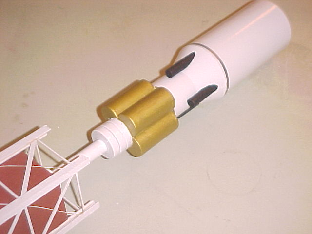
Docking Assembly
This is too difficult from me to describe. Here, a picture is definitely worth a thousand words. Figure 12 shows the parts laid out, and figure 13 shows the completed assembly. Glue the tanks to the cab making sure everything is square and centered. See figure 14
 |
 |
 |
| Figure 12 | Figure 13 | Figure 14 |
Aft Assembly
I waited until the end to install the motor mount so I had a better idea on the finished weight to choose a motor size. You may want to consider this as well.
Glue a coupler into the 3" BT50 MMT. If you want to install a motor hook, you'll need to do that now. Glue a BT50 to BT60 centering ring to the end opposite the coupler. Once dry, glue the shroud to the assembly. Glue the motor assembly to the cargo container.
Print the fin template guide. Make sure that your printer prints the right size by measuring the shown dimension after it's printed. Make four fins as shown on the fin template. Glue them to each of the four corners and to the engine shroud.
The ring was made by printing a transition shroud with the dimensions of 5" x 6" x 1" ad was made using heavy paper cardstock. I glued a second shroud over the first one to stiffen it up and soaked them both with thin epoxy.
Final Assembly
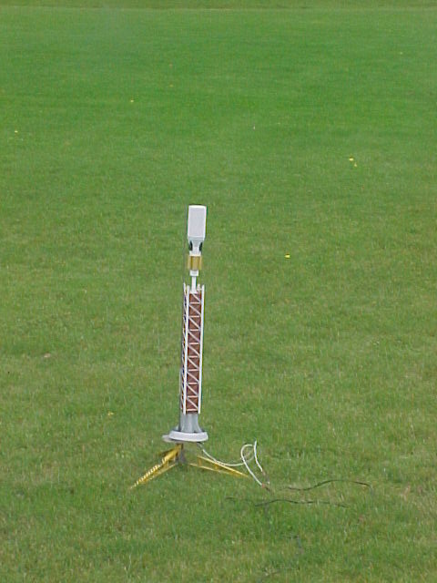
See figure 15 for this step. Paint the cargo container with red oxide primer. Sand the first coat, but leave the second coat with the mat finish. Now paint the truss with a flat white, or even a white primer. Figure 16. Once the two pieces are dry, it's OK to glue them together. You'll want to sand some of the paint off where you will be gluing them. I glued mine at each corner and at each end. Don't forget to add a launch lug as shown in figure 17. I added two 18" chutes and kept the two pieces separate on their own chutes.
|
 |
 |
| Figure 15 | Figure 16 | Figure 17 |
Finished weight with chutes is 8.4 oz. and the CG is 16.5" from the nose.
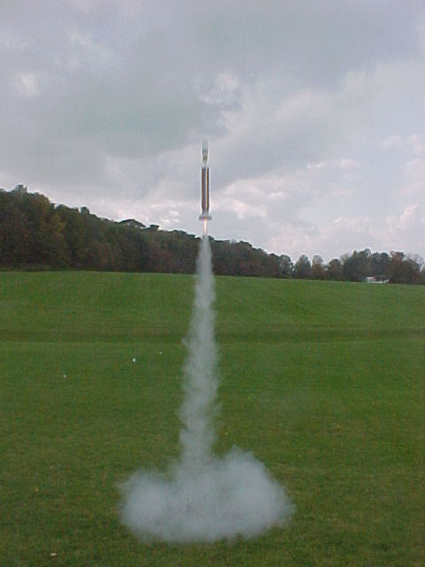
Flight
The first flight was on an E9-4. The flight was straight up to at least 800 feet. The ejection charge was late but recovery was good.
 |
 |
Sponsored Ads


 |
 |