
Presented with written permission from RocketyPlanet:
Product Review by Darrell D. Mobley
Thursday, December 18, 2008
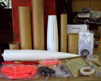 |
| The Crossbow comes with a whole box full of goodies, and promised to be a lot of fun. |
|
Recently, I had the opportunity to get my hands on Giant Leap's new Crossbow, a 4" diameter rocket with what looks like a Talon-inspired theme. In reality, the Crossbow is more akin to its cousin, the Nuclear Sledgehammer, with three fins plus a pair of mini-wings and forward canards.
At any rate, the Crossbow looked liked something I would enjoy building and I was happy to get my hands on this kit. In September, the UPS man arrived and I was off to the shop.
The Crossbow comes standard as a 55-inch long kit carrying a 54mm motor mount with a dry weight of four pounds, and the list of standard features makes it well worth the price. Standard on the kit is:
- Pre-slotted phenolic airframes
- 5-to-1 Pinnacle nose cones and tail cone
- Kevlar recovery harness protector sleeve
- Kevlar parachute protector
- Slimline 54mm motor retainer
- Dual ACME rail guides
- 48" Spherachutes parachute
- Pre-sewn nylon shock cord
- G-10 fins, wings canards
- All necessary hardware
- Crossbow decal
Also available are a number of upgrades, including a dual deployment option which includes an avionics bay, an additional shock cord, a drogue parachute, all mounting hardware, and a 24" phenolic payload airframe; as well as a Dyna-Wind single or dual deployment version; along with several recovery options and an optional 38mm-to-54mm motor adapter to fly the Crossbow on 38mm motors.
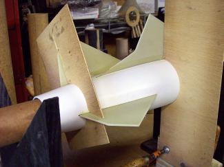
The variety of jig and templates I came up with helped get the fins on straight.
After the fins were in place and the airframe attached, it was time to fillet the fin joints.
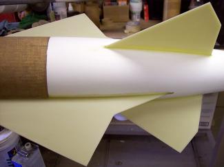
The Crossbow really has a sexy shape to it, with all those fins and wings.
 |
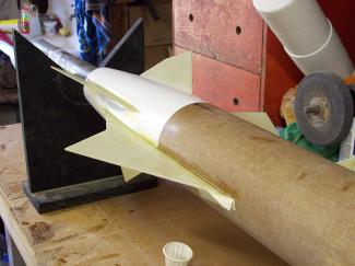
| The forward canards were moved from the main airframe tube onto the payload bay tube. |
|
Recommended motors are 38mm and 54mm I and J motors - the standard single deployment Crossbow comes with a warning not to exceed a specified motor size (an AeroTech 54/852 motor or equivalent) without adding additional nose weight to increase stability. The kit includes lead shot to put in the nose cone, but Giant Leap recommends adding more if you want to fly larger motors. My recommendation is to get the dual deployment option and eliminate the issue, which is what I did, as additional nose weight isn't needed in the longer dual deployment version - it is plenty stable due to the increased length.
One of the first things I did after opening the box and fondling all of the parts was to get right into the directions and read them from cover-to-cover. Something that has always impressed me with Giant Leap kits was the extremely thorough, well illustrated, instructions that comes with their kits. But I have a known aversion to leaving well enough alone and wanted to see what was in store for me in the days ahead.
Because of the tail cone and the number of fins, I had a little apprehension about making sure the fins were well attached, so I studied this part of the instructions really well, while dry-fitting the parts and seeing if there were areas I could make adjustments to achieve a better end result. I have to tell you, I actually cringed when I saw the illustration of a perfectly good Slimline retainer getting roughed up and covered with JB-Weld! I have always been a proponent of installing the beautifully anodized motor retainers after the rocket was painted, as an accent to the finish, and gluing it into the rocket right off the bat went against my grain. Somehow though, I knew I would figure something out.
That is not to say you shouldn't follow the instructions, this is just a quirk of my own. Following the instructions will give you excellent results that you will be extremely satisfied with. What I propose to do here, though, is give you an alternative method if you would like it, and then you could decide which way you liked best and apply it to your own build.
The instructions call for attaching the Slimline retainer to the motor mount tube, attaching the forward pair of centering rings, installing the motor mount tube in the tail cone and mounting all of that to the airframe before attaching the fins. That's a lot to accomplish in a short amount of time and the instructions expressed due concern about getting it all just right. In my mind this would also require me to have great faith in my fin-tab-to-motor-mount-tube epoxy joints, and with the motor mount tube completely enclosed in the tail cone, there was no way I could get inside to fillet the joints. Without knowing it, I had encountered what Kent from Giant Leap later described succinctly as the "Talon Syndrome."
So I created an alternative tail cone assembly process and submitted a copy to Giant Leap for future use if they so desire, and I will describe that assembly process here for you to use, too, if you like. My process allows you to build the motor mount tube, install it into the tail cone, then install the fins before installing the forward centering rings, all in individual steps rather than one quick step. In doing it this way, you can fillet the fin tab joint where they meet the motor mount tube.
You can also optionally decide with this process, as I did, to foam the inside of the fin can after the fins are installed and filleted. I did this because, in my thought process, the foam would add a stable backing at the fin-to-tail-cone joints, and prevent the fins from potentially separating from the tail cone if the tail cone were ever depressed inward around the fins.
On the forward end of the tail cone, the motor mount tube is centered in the 4" opening by a pair of 54mm birch plywood centering rings. The length of the motor mount tube is based on the length of the tail cone, the shoulder of the tail cone, the thickness of the two centering rings and the placement of the Slimline retainer flush with the aft end of the tail cone.
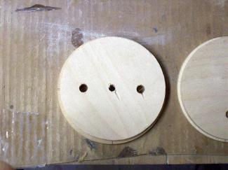
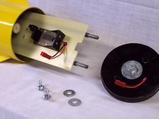
When I lined up the holes for the electronics sled, the bulk plate disks were off center. When I centered them, the holes didn't line up. What to do?
When inserted the the eyebolts into the electronics bay end caps, the eyebolts were too short if I used a nut and washer on each side. What do do?
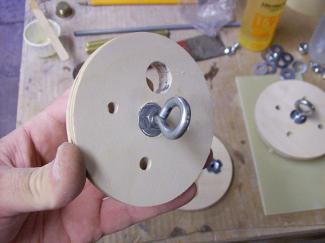
Rotating the end cap bulk plate disks 90 degrees and recessing the washer holes worked out great.
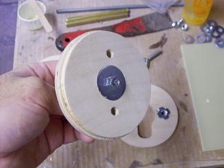
Recessing the washer holes really made a lot of sense when I saw how well they turned out.
The removable electronics sled sits snuggly between the two end caps.
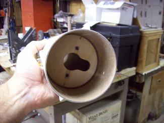 |
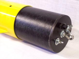
| My "receiver hitch," which holds the electronics bay into the payload section. The all-thread screws into the two T-nuts, the "keyhole" clears the main chute ejection charge, the recovery harness passes through the middle. |
|
I replaced the rear-most of the two forward centering rings, which are standard 4-inch-tube-to-54mm rings, with a 4-inch-coupler-tube-to-54mm ring. I did this so I could make a "stepped" forward centering ring, slipping it in place, dry, while I attached the fins. Then I could remove it and fillet my fin joints, and then epoxy it in place permanently when the fins and tail cone assembly was complete.
In the kit, the Slimline retainer basically forms the rear centering ring, because the tail cone tapers right down to the outside diameter of the motor retainer. But because I wanted to install the Slimline after paint, I decided to put an additional centering ring at the aft edge of the three rear-most fins, to allow me to leave the Slimline out until it was completed. And, because I had made one of the forward centering rings so that it fit inside the tail cone with my stepped design, I took advantage of this additional 1/4" of motor mount tube length to move my Slimline retainer out of the tail cone by that same distance. So rather than sitting flush, my retainer hangs out the back a little bit, which I hoped would reduce the potential for the motor's flame to toast the rear of the tail cone's finish.
Here's how I did it: I cut a 2-7/8" centering ring from 1/4" birch plywood with a 54mm motor mount hole in it. The centering ring's outer circumference was tapered to fit the inside curvature of the tail cone and was designed to mount flush with the opening of the three tail cone fin slots. For my application, this centering ring was mounted with 15 minute epoxy 1-5/8" up from the rear edge of the motor mount tube. In this manner, the fins butted up against the centering ring. Your measurement may be different, so measure twice, glue once.
I cut a 1/4" birch centering ring with a 54mm motor mount hole in it that would fit inside the forward opening of the Pinnacle tail cone. You could use a regular 4" coupler bulkhead plate, but the Pinnacle tail cone's shoulder is thicker than a phenolic coupler, so you would have to sand it down some and then cut a 54mm hole in it.
This new centering ring was epoxied to one of the original forward centering rings. No matter which way you build your Crossbow, make sure to check to see if your eyebolt/nut/washer combination clears the tail cone. I noticed mine was hitting and had to grind an area out so it would sit flush and not push the tail cone shoulder out of round.
With the epoxy on both parts dry, I roughed up the inside of the aft end of the tail cone where my new centering ring would contact the cone with 80 grit sandpaper. I also sanded the motor mount tube where the Slimline would be placed and where the fins would mount. A liberal amount of epoxy was applied to both the inside of the tail cone where it met the rear centering ring and around the circumference of the rear centering ring. The motor mount tube is slid into place, the forward "stepped" centering ring is slid on to temporarily into hold the motor mount tube in the proper position and the assembly is allowed to dry.
Once dry, and without taking the forward centering ring off, it was time to mount the fins. I used some additional 54mm phenolic couplers and motor mount tubing I had laying around to extend the motor mount tube temporarily, giving me a method to position the tail cone assembly horizontally where I could attach the fins. I wanted the mock-up to be as close to level as possible to help me align the fins better.
I used a pair of "V" blocks I had built to lay this in, which would let me rotate the tail cone as I installed the fins. Combined with additional jigs cut from luaun door skin plywood to properly position the fins at the right angles, my tail cone looked like a contortionist's day dream when the fins and jigs were in place. The bottom line is if you take you time and use your head, you can come up with the means to get your fins in the right places.
Once the fins were dry, I removed the forward centering ring which was temporarily holding the motor mount tube in the centered position. I mixed up one or two squirt of West Systems 105 epoxy and hardener and poured it into the tail cone. I then spent about 10 minutes rotating and rolling the tail cone around to distribute the epoxy all along each fin's intersection with the motor mount tube and the tail cone. I kept this up until it started to gel and then repeated the process again, making sure I had great coverage. I now felt very good about the fin-to-motor-mount joints.
My next step was to fill the area with two-part urethane foam. Giant Leap sells a version of this that would be a perfect fit here. After the foam was cured, I installed the forward centering ring for the final time, but not before I drilled the necessary hole for the recovery attachment point and bolted it securely into place.
To finish the airframe assembly, all I had to do was epoxy the airframe tubing to the tail cone assembly and admire my work. Something that jumped out at me was that with the dual deployment option, the rocket's perspective with regard to the forward canards was askew. On the standard rocket without dual deployment, the canards are mounted on the main airframe, right below the nose cone. With the dual deployment option, the 24 extra inches of airframe that makes up the main recovery area, or payload bay, makes the canards looks orphaned "way back there."
So, I "fixed" it - I epoxied up the canard slots in the main airframe and cut new ones at the base of the main chute compartment, placing the canards right above where the rocket splits at apogee. I thought it looked a lot better this way for the dual deployment version and is a simple change if you want to do yours that way. Because of the canards being mounted in the area, where the coupler that would be housing the dual deployment avionics bay is located, I opted to mount the canards by taping the inside of the slots and sliding a coupler in place to support the canards until the epoxy set. If you want to move your canards and don't use a removeable electronics bay setup, you can glue in your coupler and then glue the canards in place.
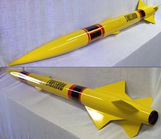
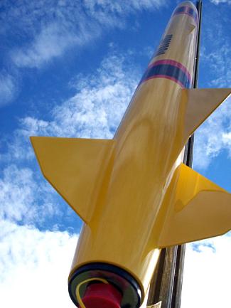
The Crossbow turned out just great, and the red and black accents certainly work well with the Chrome Yellow paint.
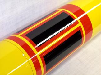
Red and black self-adhesive Monokote simplifies the addition of trim accents, and the colors work well together.
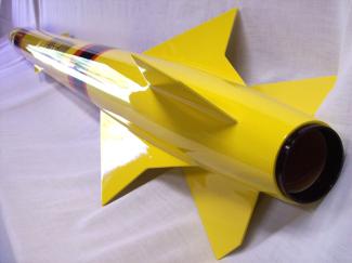 |
| This closeup shows the extended Slimline retainer peeking out from the rear, as well as the great lines of the fins. |
|
Some of you observant readers may notice that my bare airframe shots look like the tubes have fiberglass on them. Good catch! I have gotten too old to enjoy airframe repairs after completing a rocket, and I have found that fiberglassing the airframes is the best insurance against this. I could have gotten the Dyna-Wind version, and highly recommend it for those who want the additional strength without resorting to doing it yourself, but I opted to glass my tubes myself. I did this before starting construction, using one layer of fiberglass sleeving and turning the tubes on a wood lathe to sand them smooth. Just remember, fiberglassing will add to the overall weight, so you have to choose motor accordingly.
With the airframe assembly completed, my next step was to fillet all the external fin joints. The additional fins meant a couple of extra steps but the end result was starting to materialize from this box of parts, and I was liking what I was seeing. It was time to concentrate on my avionics bay, since I had the dual deployment option and I would use Giant Leap's dual deployment kit to build one of my standard electronics bay designs.
With the dual deployment version, you get all of the necessary hardware to create a nice avionics bay. The 4" version uses very stout 1/4"-20 threaded rods, .062" G-10 for the altimeter mount, and dual 1/4" end caps that make up a solid 1/2" thick cap for each end. One thing I noticed however was that the end caps seemed to have mismatched holes in them - if I matched up the holes, the inner cap wasn't centered on the outer cap. If I centered the inner cap on the outer cap, the holes wouldn't line up. The center hole would line up, but the holes for the electronics sled didn't. What to do?
My solution: I just rotated the holes 90 degrees, applied epoxy, centered the inner cap over the outer cap and bolted it together with a 1/4"-20 bolt in the center hole until dry. I then could redrill my electronics sled holes and go on.
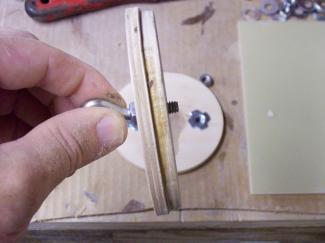
Another thing I noticed was that if I put a nut and washer on the eyebolt and stuck it through the end cap, there wasn't enough room for a washer and nut on the other side. I couldn't do without the washers, which help spread the load of the recovery event, so what to do?
My solution: I took a couple of flat-bottomed spade bits, one the diameter of a regular 1/4" flat washer and the other the diameter of a 1/4" fender washer, and used them to recess the holes in the center of the end caps by the thickness of the washers. The result was a flush mounted washer on both sides, a cleaner solution that doesn't protrude into the electronics bay area. I was very happy with the solution.
The dual deployment kit comes with a regular coupler, which is about 1/2" longer than the supplied G-10 electronics mounting board even when you take into consideration that the end caps protrude into the electronics bay 1/4" on each end. I do not prefer a 1/2" of slack in my electronics bays, as I do not want my electronics being able to bang around. I like them mounted securely with little movement.
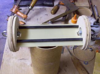
The removable electronics bay allows for easy access to the electronics inside.
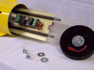
With the hood up, you can see the Missile Works RRC2-Mini and quick disconnect for the drogue charge.
On the back side, the Newton's 3rd 9V battery holder is easy to get to, the main charge holder tube in the upper left.
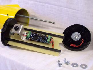
The ability to take it all the way apart makes access easy and service simple.
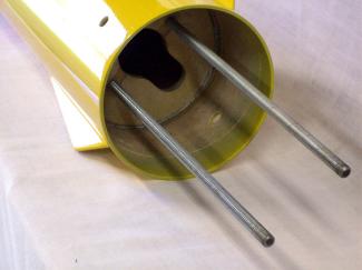 |
| The "receiver hitch" is what holds it all together. |
|
In my design, the G-10 mounting board runs from one end cap to the other, and I cut down the coupler tube to make it the length to fit this space. The piece of coupler tube I cut off was then used to make a "receiver hitch" which is mounted permanently in the payload tube.
I replaced the short brass tubes that come in the dual deployment kit that are used to mount the electronics mounting board with carbon fiber arrow shafts. My new tubes extend 1/4" longer than the G-10 mounting board on each end. This allows them to be fitted into the inner end cap bulk plate on each end, adding strength to a collapsible design that comes completely apart. So where you see the black carbon fiber tubes in the accompanying photos, they extend halfway through each end cap - the holes in the end caps are sized accordingly, larger on the inside, smaller on the outside. I attach the G-10 to the carbon fiber tunes with medium CA, full length, both sides. The tubes or G-10 are not glued to either end cap.
The "receiver hitch" is made by cutting a 4" coupler tube bulkhead plate, adding a 29mm hole in the center. To this is added two holes which correspond with the holes in the electronics bay end caps. These holes will have two 1/4"-20 T-nuts inserted that the electronics bay all-thread will screw into.
This bulk plate is epoxied into the cut-off piece of coupler tube previously mentioned and will mount permanently inside the payload tube, to receive and hold the electronics bay. Before doing that, a "keyhole" recess is cut to one side of the 29mm center hole, as shown in the accompanying photos, to clear the main ejection charge holder tube, which mounts in the forward end cap.
I make my ejection charges for this rocket out of 1/2" launch lugs housing flash bulbs. The main ejection charge holder tube is a 3" long piece of 3/4" aluminum tubing, 1/16" wall, with a 1/4" thick plywood aft plug, epoxied into the "back" side of the forward electronics bay end cap. The "back" side is identified as the side opposite of the carbon fiber tubes, and is pointed out in an accompanying photo. The "front" side has an aluminum bracket fashioned from 1-1/4" wide, 1/16" wall, aluminum strap and holds the altimeter switch. The opposite end 0cap used a regular electronics terminal wired through the cap to connect to the drogue ejection charge.
Access to the electronics bay power switch is through a 1/4" vent hole, which is placed directly over the switch. Careful measuring and drilling will put your holes in the correct places. Another matching 1/4" vent hole is placed 180 degrees on the rear of the payload compartment.
For recovery, I would be using the new Missile Works RRC2-Mini, a wonderfully simple to use altimeter with a small foot print. Housing the 9 volt battery that powers the altimeter is a Newton's 3rd 9V battery holder. I like this holder because it sits up off the backing plate, which allows you to slip a nylon wire zip-tie under and around the battery to secure it in place.
Field assembly of the electronics bay is a snap, access is wide open, and you can replace any of the parts without having to majorly rebuild any part of your electronics bay. That is what I like about this design. No hatches, doors, external switches, screws, etc., are needed. It's just a clean and simple design that works.
With the electronics bay completed, it was time to turn my attention to getting the Crossbow ready for paint. I had previously decided to paint the rocket using NAPA's Martin Senour Crossfire automotive acrylic enamel paint with urethane hardener, and settled on a bright Ford color called "Chrome Yellow."
The rocket was prepped with Martin Senour automotive gray primer, and the cycle began: prime, sand, repeat. I wanted to get a smooth finish, but more importantly, I wanted to get a seamless surface where the tail cone met the airframe tube. The only way to do that is to prime and sand using a flat sanding block. It may be a lot of work, but the end result is worth it.
I painted the rocket outdoors, behind my shop, on a bright clear October day. Even with the still winds and clear skies, there were still a couple of kamikaze bugs who wanted to spend their lives riding rockets. Fortunately, all that got embedded seemed to be feet and legs, and some polish and wax got most of that out.
Over the bright yellow finish, I added red and black self-adhesive Monokote trim accents that I cut out myself, along with the Crossbow decal that came with the kit. When you install the decal, use an Exacto knife to remove the excess clear tape outside of the lettering. Next was the Slimline retainer and the ACME rail guides.
The author poses with the Crossbow, both sporting loud yellow wrappings. The Crossbow is loaded with a J260 Skidmark demo motor, made for the CTI Pro54 2 grain casing.
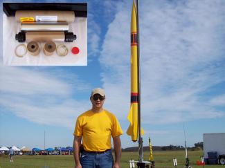
Every star wants to pose for a glamour shot.
The Crossbow takes flight on a column of sparks.
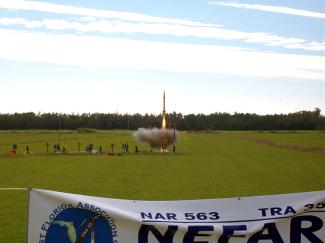 |
| The Crossbow's J260SK maiden flight. |
|
I have to tell you, I did not follow the directions on how to attach the rail guides and I popped one on the first launch. On previous builds, I have tried to use the sticky tape that comes with the ACME guides, but it would get hot and fall off! This time, I just CAed the guides right to the rocket, and it snapped off, clean as a whistle. I am seriously thinking about just taking a countersink and drilling a small hole right in the middle of the guides and using short screws to attach them. So pay special attention to the ACME guides if you use them, they require special attention to get the stuck and keeping them there.
The bright yellow Crossbow got a lot of attention at Bunnell Blast, held on Saturday, November 8th and hosted by the North East Florida Rocketry Association in Bunnell, Florida, just northwest of Daytona, Florida. NEFAR enjoys acres of beautiful sod as a launch site, and are the best group to launch with you can find.
For the maiden flight, I was offered the opportunity to also make a maiden flight of a CTI J260 Skidmark, a new two-grain motor configuration cooked up by the guys north of the border. I can't say enough about the ease of use CTI motors offer the users. Assembly was so simple, just stick in the parts and screw on the closure. Cleanup was just as easy.
The weather was as perfect as I have ever seen at a launch, with nothing but clear skies, light winds from the north, and lots of sunlight. I prepped the motor and put it in the Crossbow, and then prepped the recovery and electronics. With my electronics bay design, access was very easy, which is what I like about 4" rockets - you can get your hands in there.
On the pad, after the obligatory creator-creation photo op, the Crossbow just looked majestic sitting there. It was a very nice design and got lots of comments from people walking the flight line, and now was the moment of truth. Continuity was checked, the altimeter armed, and then back to the LCO desk.
At ignition, the big J Skidmark roared to life and took off for the north, appearing to cone a little. I couldn't decide if it was trying to fly on the wings or if I got a weird thrust vector. I would later learn that my aft rail guide snapped off on the way up and contributed to the off-vertical launch. The Crossbow would streak to 1974 feet before landing safely in a pasture across Bunnell Road.
My initial review upon reaching the landing site was the Crossbow was in excellent condition, with just a few cosmetic cuts and contusions. One of two things occurred at deployment, either the recovery harnesses needed to be longer or the ejections charges were too large. I subscribe to the school of blow 'em up or blow 'em apart, so it could very well have been the latter. At any rate, it was a beautiful flight and the Crossbow performed admirably.
Loaded with style and grace, the Crossbow will be sure to generate a lot of ooos and ahhhs from onlookers. It is an excellent kit for those who like that winged look, those who are desirous of more than 3FNC, or those who enjoy something out of the ordinary. I heartily recommend it and think you will enjoy the build. While I am at it, I also recommend the dual-deployment version, as it reduces the typical instability issues of shorter rockets with large motor mounts, as you are going to most certainly want to put larger and larger motors in it just to see the results. The Giant Leap web site says this rocket is not for the faint at heart, but it really wasn't that big of a deal if you are able to read things through and follow instructions, or know what to do should you want to try something different. If you are up to the challenge, give the Crossbow a shot.


D.B. (March 31, 2009)