CLICK PICTURE TO GET FULL SIZE
 |
 |
 |
 |
 |
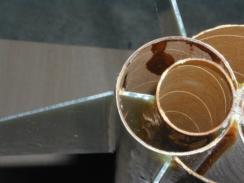
| Step 11: Install the motor tubes. (in my case, I used 6" tubes, however, if you have 12" tubes then they could extend up into the nose cone shoulder). Epoxy each tube in place and then use ample epoxy fillets on both sides by using a dowel (or chop stick) to get the epoxy all the way to the top of the motor tube. Again, be sure they are aligned (perfectly centered). NOTE: the main fins were cut for a 29mm motor tube and will require modification if you choose to use a different motor tube. NOTE: 12" motor tubes would be best for motor ejection configuration. You would then want to install the motor tubes prior to installing the 1.9" cones (step 10). Once installed and flush with both ends of the 1.9" tube, then you would want to fill the top section filling the space between the motor tube and 1.9" tube wall (see technique 5) |
Step 12: Using the template place a mark on left and right side of the 1.9" assembly. Extend that line using a door jam. Make a mark on the line a 1/4" from the back end and then measure up the line another 5 7/8" and make another mark. Using a very sharp (this may be your third blade) hobby knife, cut about 1/16" of an inch down inside of the line and 1/16" down the other side within the two marks you made. Test fit the main (larger) fins for fit. Make sure the body tube(s) don't become distorted. When the fit is correct, put epoxy on the root edge and slide it through the slot until is meets the motor tube. Be sure to support the rocket and fins to ensure proper alignment. (90 degree angle from body tube). Repeat on the other side. Fillet the INSIDE (DO NOT DO THE OUTSIDE YET!)of the tube and along the motor tube. WARNING: Keep the last 1/4" of the 1.9" tubes (inside) and the motor tube free of epoxy. | Step 13a: Rough up the epoxy fillets where the
2.6" tube flap was glued to the 1.9" tube assembly using 80-100 grit
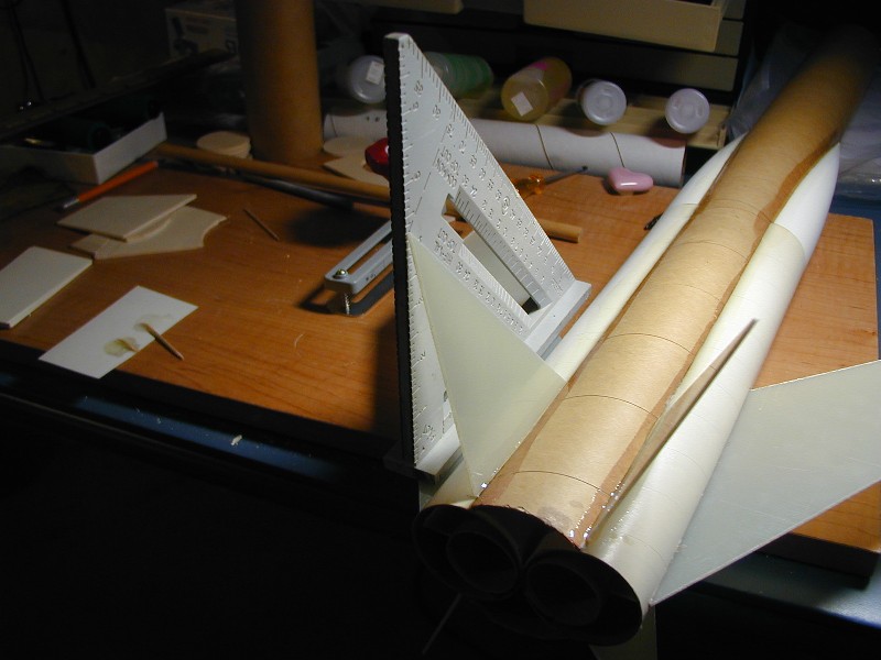
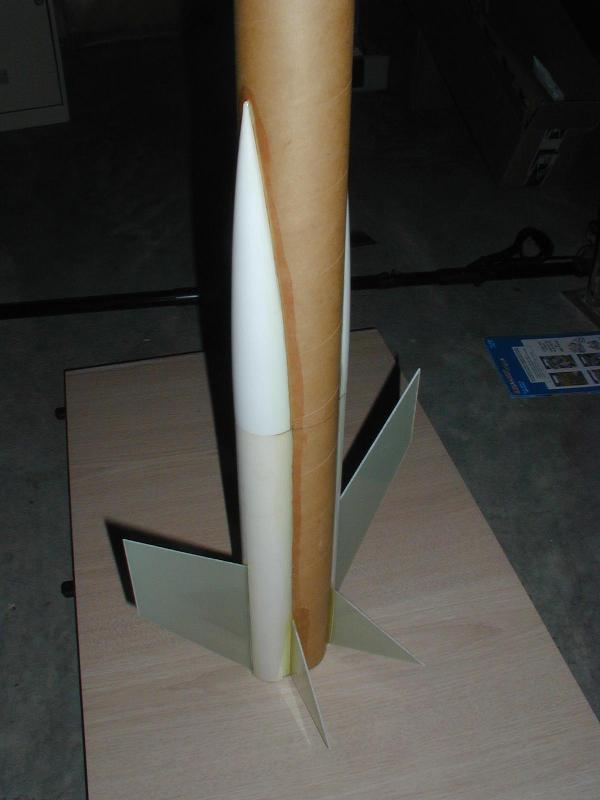
paper. Mark each joint 1/4" from the bottom of the rocket. If you don't have a Rafter Angle Square, then go buy one (Home Depot has them). You'll use it in rocketry and it really helps with this rocket. Place the Rafter Angle Square on the one of the main fins so that edge is up against the 1.9" body tube. See Picture 1 below to get an idea of the finished angles |
Step 13b: Apply epoxy the root edge of one of the smaller fins. (verify direction of the fin from this picture . . . it really doesn't matter which way, just make them all the same) Take the small fins and place it on the joint made from the 2.6" tube flap and the 1.9" tube at the 1/4" mark. (expand this picture). | Step 13c: Lean this small fin against the Rafter Angle
Square, then slowly slide the Square out until the fins tip is at the 4
1/4" mark while the Square is still parallel with the seam. (expand this
picture). Be sure to watch that your fin stays aligned in the seam. Do
this for all (4) fins. If you don't have a Rafter Angle Square then the small fin tip should be about 4 1/2" from the large fin when measured between 3/8" and 1/2" out from the seam. |
 |
 |
 |
 |
 |
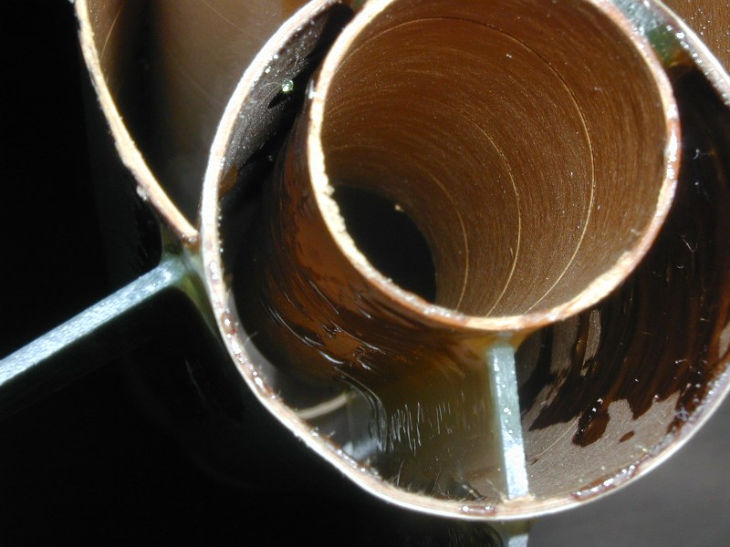
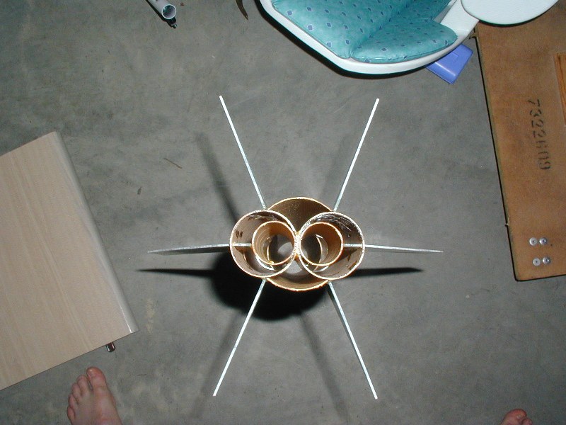
| Step 14a: Fillet the heck out of it. Inside, outside, large fins, small fins, and the motor mount. WARNING: Keep the last 1/4" of the 1.9" tubes (inside) and the motor tube free of epoxy. | Step 14b: Same idea, but this picture shows where I didn't keep the last 1/4" of the inside of the tube and motor tube clean. I had to clean that up later. | Picture 1: Just showing the alignment of the fins. WARNING: Your most vulnerable joint is where the four (4) smaller fins attach to the body tube union. Be sure to use ample fillets to provide the necessary strength. |
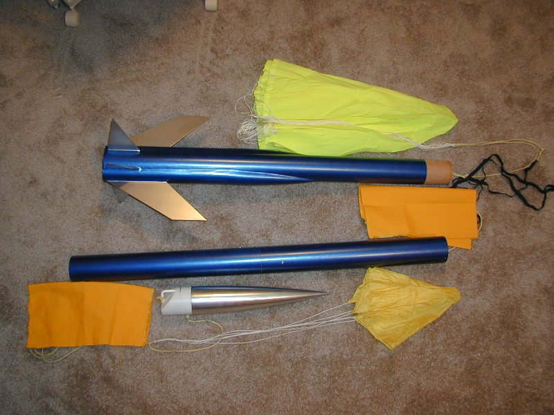
Picture 2: Just another angle | Picture 3: This shows the electronics bay in place holding the upper (main chute bay) and lower (drogue chute bay) body tubes together. I used a bulkhead on the top of the main body (with fins and motor mounts). In this configuration, the ejections based at the electronics bay "pushes" out the main body at apogee and then "pushes" out the nose cone at close proximity. |