Estes SuperNova RF Video Payloader
Scratch - SuperNova RF Video Payloader (Modification)
Contributed by Bob Weiss
| Manufacturer: | Scratch |
Brief:
Upon returning to the rocketry hobby a few years ago, one of the first "serious" projects I wanted to
attempt was an onboard video camera system. Most of the commercial systems being used in LPR rockets (such as the Estes
"Oracle") utilize onboard digital recording and suffer from poor video quality and limited recording time.
The severe weight, size, and power consumption limits inherent in payloads for LPR-class rockets pose considerable
engineering challenges. I designed and built this system before the recent loosening of FAA reporting requirements and
wanted to keep total rocket weight low enough that no FAA involvement was needed. Gross weight at liftoff was not to
exceed 1 pound.
Construction:
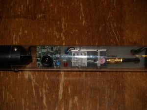
The transmitter I used is a commercial unit, Model AVX900T4, sold by SuperCircuits, Inc., a large supplier of CCTV and surveillance video equipment. It is designed for operation from 12VDC power and produces an RF carrier output of 500mW. It accepts standard NTSC video and baseband audio inputs and provides RF output via an SMA connector. This is a very small device (1" x 2" x 3/8") or approximately the size of a typical rocketry altimeter such as the MAWD. Transmitter weight is approximately ¾ ounce. Use of this unit requires a Technician class or higher amateur radio license in the USA. The manufacturer claims a 1 mile range under optimal conditions.
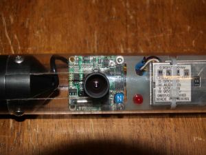
The camera itself is a 1/4" CCD color "board camera" salvaged from a discarded video baby monitor. Similar units are widely available from electronics surplus dealers and online auctions. I have purchased similar cameras on eBay in 10-piece lots for around $50, or $5 per camera. Typical power requirement is 12VDC at a current of around 100mA. Output is standard NTSC composite video. Some of these camera modules also incorporate a built-in microphone and provide an audio output channel.
Providing power to the transmitter and camera turned out to be one of the more difficult challenges in this project. Total system current draw is approximately 350mA at 12V, and I wasn't able to find any 12V battery packs that would provide sufficient current and still fit inside the payload compartment. Fortunately, both the camera and the transmitter were capable of operation from 9-14 VDC, so I chose a common 9V battery as a power source. Because the ~350mA current draw is quite high, the use of a battery that is designed for high demand applications is recommended. Rechargeable NiMH and Li-Ion batteries are available, but I have been able to get 2-3 flights from a fresh Duracell or Energizer at much lower cost.
As stated above, the camera module is designed for operation from 9-14 VDC, and the lower specified limit is truly the limit. After some strange behavior during cold weather testing, bench tests showed that the camera suddenly stopped functioning (giving a black screen) once the power supply dropped below 8.9V. Because cold weather or an even slightly used battery may result in an output below this threshold, some means needed to be found to keep the camera power steady as the battery output dropped. A small DC-DC power converter from XP Power Corp (part number JCA0205S12) was chosen as a "drop-in solution". This small, lightweight module produces a regulated 12VDC output at up to 170mA over an input voltage range of 4.5 to 9V. The output of the module was used to power only the camera module, with the transmitter operating directly from the battery. The camera now provided steady video over the entire life of the battery, down to below the point where the transmitter ceased to function (around 7V).
The transmitter module was provided with a small flexible whip antenna, which I originally planned to mount inside the hollow plastic nose cone of the rocket. Testing soon revealed that the black plastic nose cone actually acted as an RF shield, reducing transmitted signal strength substantially. I can only guess that the black pigment in the plastic is carbon black or some similar conductive material. After toying with the idea of mounting the antenna externally on the tip of the nosecone (which looked really cool but would most likely been damaged on landing), I opted to fashion my own nosecone from polystyrene foam and incorporate a pair of copper tape dipole antennas into the outer surface of the cone. The cone was made in a non-specific ogive shape (sanded to shape in a lathe) then coated with a mixture of West System epoxy and phenolic microspheres for strength. After curing, the epoxy surface was sanded again and the copper foil tape patterns applied. A length of RG-174 miniature coaxial cable was used as a feedline for the antenna and brought out at the base of the nosecone. After testing and tuning the antenna for minimum VSWR, the copper foil tape was overcoated with 2 layers of epoxy for weather resistance. A male SMA connector was installed on the transmitter end of the feedline.
The receiving end of the video system consists of a receiver/antenna, video digitizer, and a laptop computer for recording. The receiver is also from SuperCircuits (model AVX900R1) and uses a simple whip antenna which was included with the unit. Power for the receiver is 12VDC provided from the same battery that runs my launch controller. The receiver provides standard composite video/audio outputs and will work with any NTSC compatible monitor, VCR, or other video device.
The receiver feeds a signal to a USB video digitizer module, which converts the analog video signal into a digital format for recording. The module plugs into the USB port on my laptop (Dell Inspiron 5150). The included software package allows the recorded video to be saved and edited in various formats, including MPEG4, .avi, .wmv, and .flv. Unfortunately, the software is only available for Windows and no Linux drivers for the hardware are available to my knowledge.
Flight and Recovery:
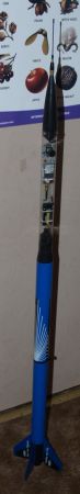
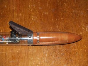
The rocket itself is an Estes #2155 SuperNova Payloader. It's currently out of production but still available from
internet sellers. The rocket incorporates a long clear plastic payload section (BT-55 size) which houses the camera,
transmitter, DC/DC converter, power switch and indicator LED. All components are mounted to a carrier plate made from
G10 fiberglass sheet, which slides into the payload tube. The main rocket body is BT-60, and the 9V battery is housed
inside the hollow plastic transition section. The rocket required several modifications to adapt it to the camera
project and increase reliability. The booster section was fitted with a piston ejection system to assure deployment of
the booster parachute. The stock elastic shock cord was discarded in favor of a 1/8" braided Kevlar cord fitted
with stainless steel snap swivels. The shock cord mount was replaced with a #10-32 screw eye into the plastic coupler
between the booster sections. The booster section recovers on a 18" nylon parachute, while the camera section uses
a 24" nylon chute. The plastic fin can/motor mount assembly is essentially a stock build but in retrospect should
have been modified to accommodate "E" length engines. The plastic twist lock motor retainer cap was modified
by enlarging the internal diameter slightly (bored on a lathe) to accommodate the thrust ring on a 24mm reloadable
motor case. Initial test flights were without payload on the Estes recommended D12 engine. These flights showed some
weaknesses in the stock ejection system--namely the booster chute failed to deploy consistently, resulting in a couple
"core samples"--prompting the use of piston ejection. Subsequent test flights with a simulated payload weight
pointed out the need for more powerful engines than the Estes D12 due to low altitude and severe weathercocking issues.
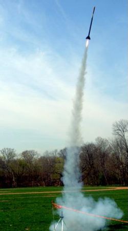
Successful test flights were made using AeroTech E15-4 and E30-4 single use APCP motors, which reached ~1000' AGL.
Initial camera flights used the E30 motors before moving up to F24 reloads in a 24/40 RMS case. The F24 gives a nice
flight to ~1800' AGL. Optimum ejection delay seems to be somewhere between the 4 and 7 second options that AeroTech
offers. The 4 second delay occasionally causes a minor zipper, while the 7 second is well past apogee at ejection.
 Video results have been quite impressive for the use of such simple antennas on the receive end. Very
little signal breakup is seen on most flights. I usually set the camera for a downward view of the ground using a small
mirror attached over the lens with a removable balsa fairing. Removing the mirror gives a view out to the horizon,
which usually isn't as interesting. A typical flight video is
posted online here.
Video results have been quite impressive for the use of such simple antennas on the receive end. Very
little signal breakup is seen on most flights. I usually set the camera for a downward view of the ground using a small
mirror attached over the lens with a removable balsa fairing. Removing the mirror gives a view out to the horizon,
which usually isn't as interesting. A typical flight video is
posted online here.
Summary:
Ideas for future refinements include using the audio channel to transmit telemetry data (from an accelerometer or
other transducer) by converting the sensor output into a variable frequency tone. I am also thinking about building a
bigger camera carrier rocket for this system and using the data output from an altimeter to provide a real time,
on-screen display of altitude during the flight. Higher altitude flights will probably necessitate a better receiving
antenna with some directional characteristics.
Component Suppliers:
Sponsored Ads


, 2024 Graduation Decor, Graduation Gifts, 2024 Graduation Party Decorations, Black & Gold, 2024")


 |
 |