Scratch Fireball XL5 Original Design / Scratch Built
Scratch - Fireball XL5 {Scratch}
Contributed by Dick Stafford
| Manufacturer: | Scratch |
 Brief: This is a fantasy-scale model of the Fireball XL5 spacecraft, which was the subject of an old TV show. I have seen a photo of a high power Fireball model, however, my motivation came from a thread in the ‘Rocketry Forum’. Inspired by a model being developed by Steve Rogers, I began thinking about the pile of parts that I got from LOC as my Descon 9 prize and decided to give it a shot. I made several minor adjustments to the scale factor to fit the parts I had on hand, but the overall look is correct.
Construction:
Fireball XL5's producer was Gerry Anderson, who also created the 'Space1999' and 'Thunderbirds' series. Like most things in the universe, the Fireball has quite a few web sites dedicated to it.
If you are interested, here are the main sites I referenced. From these, you can access many more.
 (1) Steve Rogers' Fireball XL5 site [dead link]
- (2) Steve Rogers' Fireball construction page [dead link]
- (3) A comprehensive site
- (4) Fireball XL5 plans
I decided to base this model on LOC 2.5" and 3" tubes with the 2.5" tube running full length. I conveniently had a Fat Boy nose cone, which fit the LOC tubing and provided a good basis for the Fireball cone. I chose a 29mm motor mount since I knew the rocket would end up being heavy for its size. I was right. Finally, I decided to use foam board for the fins. It is light and easy to work with, I had it available, and I generally seem to be stuck on this somewhat unconventional material. It has worked well for me up to this point, and it will be interesting to see if it will hold up to the forces exerted on the large side pods. Taking the hint from Steve Roger's site, I took the plans available in reference #4 and printed out a set of full-scale fin templates. The following is a summary of the construction techniques I used.
 Side pods - The pods are made of three layers of foam board with a basswood support in the middle layer. The edges were sealed with Fill 'n Finish.
Side fins - These are foam board structures with a balsa leading edge. Structural support includes a basswood spar, an idea I also borrowed from Steve Rogers. The spar fits into slots on the side pods and extends through both the 2.5" and 3" tubes to the motor mount. To support the whole structure, I filled the fin units with 2-part foam from Giant Leap.
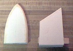 Top fin - Since it will not be subject to the same forces (takeoff and landing) as the side fins, this fin is not foam filled. Instead, I added some internal ribs and two small dowels, which extend into the 3" tube. The leading edge is also reinforced with a 1/8" dowel.
Nose cone - Due to its questionable aerodynamics, I projected that the nose cone would end up being quite heavy and would require a sturdy tip. The tip consists of a suitably sized paper cone printed from VCP. It is thoroughly soaked with CA and filled with 2-part foam. The foam kept trying to clog the small hole and I wasted a couple of small batches, but ended up working out well. The fins on the nose cone are 3/16" balsa.
 Front transition - For the long 2.5" to 3" transition at the front of the body, I ended up just using a poster paper wrap patterned from a VCP template. I decided this would suffice since it probably would not take too much of a beating. Since the section of 3" tube was about an inch short, I made this transition about one inch longer than I was supposed to be.
Rear transitions - The rear of the rocket has two transitions. The first (3" to 2.5") is made from poster paper and the second (54mm to 29mm) is formed from epoxy filler. The latter was scavenged from the remains of a previous project.
Motor mount - The motor mount is pretty standard and provides both the attachment point for the ¼" Kevlar shock cord and a bolt to provide positive motor retention.
 Trim - The remaining pods and ribs were made from balsa stock, bamboo skewers, 2 sizes of wooden 'half- eggs' from Michael's craft store, a couple balsa nose cones, BT-5 tubing, tubes from AT First Fire igniters, and small cones turned from 3/8" dowels. Other than some high skill level Estes kits, I've never built a rocket with this much detailing.
Stability - I first made a 'what-if' design in Rocksim to get a feel for the effects of the forward fins. I decided the CG would have to be between the transition and the side fins. Then, I loaded a G80 (the biggest engine I'd ever want to use) and some nose weight. With the CG approximately 2" in front of the side fins, the spin test was successful. Then, I buried the eyebolt and lead weights in 2-part foam.
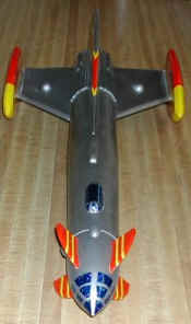
I primed the model with Plasti-Kote white sandable primer and painted it with Testor's Stainless Steel Metalizer. I did a little buffing and then put on a layer of clear sealer. The red and yellow trim is Trim Monokote. I used small pieces of blue laser-finish contact paper to simulate the windows on the nose cone and top cockpit. This ended up looking pretty nice IMHO.
Here's my procedure for applying the Trim Monokote:
- For the curved sections, carefully measure and mark the points along the edge of the fin where the trim will go.
- Cut a 1" wide piece of trim that is the exact length of the path to be covered. I would cut a piece a little long, lay it onto the curve, and then trim it to the exact length.
- Cut slits along each side, leaving about 1/8 in the center. I started cutting them approximately every 1/8 inch on the tighter bends, and up to every 1/2 inch as the curve straightened out.
- Remove the backing and start installing it on the edge of the fin. Work your way along, laying down the tabs as you go.
- For straight sections, I just cut rectangular strips that overlapped the face of the fins ~ 1/2 inch. The width varied with the thickness of the fin being covered.
- Using the templates used to make the fin itself, cut pieces of Monokote that are ~ 1/4 inch smaller in all dimensions. That way, these pieces sit on top of the strips that have already been installed, but do not go right to the edges of the fin. Note that my printed templates also showed the markings, so I could use them for the stripes too.
Flight:
For the first launch, I decided to go with a G40-4 instead of a G80. Using the conventional wisdom of how to size an engine, this would make the flight slightly underpowered. However, I was also concerned about the side pods holding on and decided the 3.7 thrust ratio would be OK. I flew the model at the MDRA high power launch on 4/6/2002. I haven't been as nervous/excited since 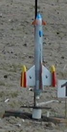 my Level-2 flight. For a small rocket, I had a lot of time invested! I bolted on a motor retainer, installed a Kevlar chute pad, and used the 42" chute from my DG&A Lazarus. The winds were stiff and the Fireball weather cocked severely. It also had a corkscrew motion, which got more pronounced after burnout.
Should have used the G80. However, it did no skywriting, flipping end-over-end, or other extreme behavior. The chute came out in plenty of time but the late ejection caused a 2-3" zipper. This is easily fixable and I will try her again on a G80.
Summary:
This was a fun and rewarding project. The foam board design worked fine, but after adding basswood supports, filling the fins with foam, etc., I am not sure how much weight I saved. Despite the zipper, I deem the first flight successful. I could have flown it again but decided to wait and fix the zipper - to cold and windy and I had other stuff to go up.
Other:
If you ever try to build one of these, be aware that slight differences in the forward fins can make a *large* difference in the stability of the model.
Sponsored Ads


")

")
 |
 |