| Construction Rating: | starstarstarstarstar |
| Flight Rating: | starstarstarstarstar |
| Overall Rating: | starstarstarstarstar |
| Manufacturer: | Aerocon Systems  |
Brief:
Flippitwin is an unusual two stage rocket from Aerocon Systems. It uses the
unusual folding-fin rocket Flippifin sold separately as a single stage rocket
as the sustainer. The sustainer is boosted by a booster tube and the sustainer
squirts out of the tube when the sustainer motor is fired. Because the booster
comprises the bulk of the two stage rocket, the booster must have a separate
recovery system necessitating the use of electronics for staging and optionally
for recovery.
Construction:
Bob Fortune sells the kit with or without a flight computer and recommends that
the kit is designed to work well with the inexpensive G-Wiz LC computer, an
accelerometer-based computer which does not have a barometric sensor. I
purchased the G-Wiz LC computer since this was to be my first use of
electronics in a rocket and I did not already own a suitable altimeter or
timer. The kit came packed in a large mailing tube with all the parts in
perfect condition and a couple of extra military surplus chutes and a
"Remove Before Flight" flag as extra treats thrown in.
I spent some time puzzling over the instructions, trying to recognize any hidden complexities in the design. I had previously built Flippifin so I went straight for the booster construction.
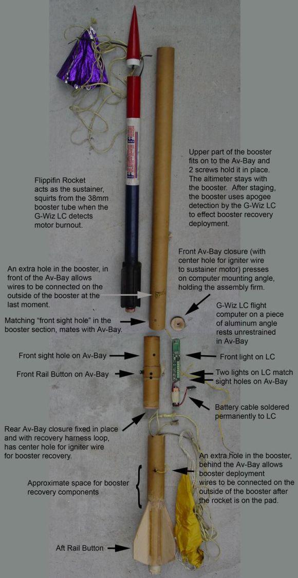
The kit contains 3 sections of 38mm phenolic tubing. A long piece is the forward end of the booster and houses the sustainer rocket. The medium length piece is the aft end of the booster which takes the 29mm motor mount and fins. A stubby piece is part of the avionics bay (Av-Bay) which acts as the coupler between the two larger sections of the booster. An assortment of screws and centering rings are included so that everything needed to make the booster is ready to go.
The instructions were clear. I dry fit all pieces and everything matched up perfectly. In a few places they suggest doing things "best way", which I took to be code for "don't worry, you'll figure it out". With a few nimble twists and turns of the brain I managed to stumble upon the appropriate workable solutions and enjoyed fiddling with the construction. Contrary to the instructions, I left the attachment of fins until the very last but this makes no difference in the end. The fins mount to the booster using surface mount technique which is perfectly adequate. I used 20-minute epoxy throughout the build and gave the fins a beefy fillet. The kits comes with some unique shock cord material which I recognized from my previous experience with Flippifin. I like the material (called fiberglass tow I think), but I thought that the booster recovery harness needed to include about 3 times as much shock cord so I substituted 20 feet of Kevlar® cord. It later proved to be a challenge to get the entire recovery system stuffed into the bottom part of the booster as the extra cord added some extra bulk.
The construction of the Av-Bay is the most important part of booster construction and Bob makes this very simple. In addition, all of the parts fit so well that it was hard to go wrong. When finished, the Av-Bay should contain a minimum of one peephole for viewing the power indicator light on the flight computer (the front sight hole). Since the computer does not use a barometric sensor, the sight hole does not need to act as a vent hole, so presumably there are other possible construction techniques that could be employed in the Av-Bay construction. I chose to drill two more holes in the Av-Bay so that I could also view the two rear pyro channel indicator lights on the flight computer. At the time of launch I forgot to look at these, but since everything went well, I assume that I did not miss much. I mounted the computer on the small length of aluminum angle as suggested. The length of angle was perhaps 1/8 inch too long, so it did not allow the front Av-Bay closure to fit securely. The instructions suggest shaving the aluminum angle down until you get a perfect fit. I chose instead to carve an angle shaped recessed groove into the front Av-Bay closure with a pocket knife until I had a very tight fit. In the end, the front closure fit snuggly and the groove centered the computer in the Av-Bay, holding it slightly away from the walls of the tube. When the rocket is fully assembled, the forward Av-Bay bulkhead just sits in place, pressed in place by a thrust ring that is installed up inside the forward section of the booster. I opted to use two small screws to secure the front section of the booster to the Av-Bay, but the instructions suggest that tape could be substituted and I agree that tape should work fine.
After completing construction of the booster, I began to puzzle over how to actually prepare the booster and Flippifin for flight. The flight computer is intended to sense booster motor burnout and ignite the sustainer motor from pyro channel 1. The flight computer stays in the booster section. The booster is then recovered either by the booster motor ejection charge or by the addition of an ejection charge controlled by the flight computer which senses booster apogee and fires pyro channel 2. I had no experience in the use of avionics, but I had a distinct impression that there should be a way to arm the system after putting the rocket on the pad, rather than traipsing around the prep area with a fully armed rocket. I chose to add a computer controlled booster section ejection charge, thus creating redundant ejection for the booster. The sustainer ejection would come from the sustainer motor.
I did not have any sort of switch to attach to the power supply for the flight computer, so I decided that I would wire the live computer to the two e-matches out on the pad. This meant that for the sustainer igniter needed a wire coming from the computer and hanging outside of the booster and the booster ejection charge needed a wire coming from the e-match to the outside. Thus, I drilled an extra hole in each of the upper and lower sections of the booster for each of these connections to be made by twisting wires together on the outside of the rocket. Only later did it occur to me, after someone else suggested it to me, that a simpler arrangement would involve a simple spliced power supply wire. However, my arrangement of wires hanging on the outside of the booster gave me an advantage in that I had control over all wires from the outside of the rocket during assembly, so I could easily tug on the wires during assembly and avoid getting the wires snagged or bunched up in the process.
Overall, the Flippitwin booster construction was straightforward and enjoyable. I do not discuss the construction of the sustainer here, but Flippifin construction is also a great deal of fun. Any mildly adventurous person who has at least a minimum of model building experience can easily construct both the booster and the sustainer. In my experience Flippifin has proven to be a rugged and very nice rocket, so I believe that Flippitwin will also provide many enjoyable launches.
Finishing:
I finished the booster only a few days before a scheduled club launch so I
decided that I did not have time to paint it. I built the Flippifin sustainer
that came with the kit, making this my second Flippifin rocket but I did not
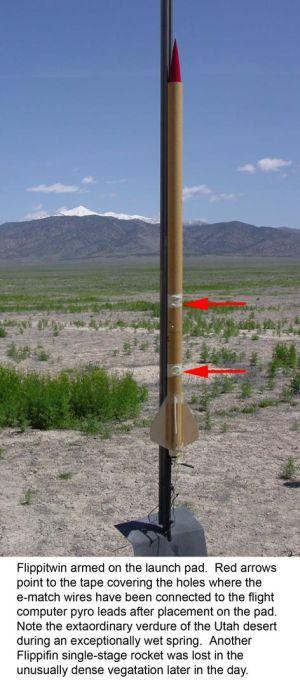
paint it either. This was a mistake, since I decided to fly the unpainted
Flippifin as a single stage rocket later in the day and ended up losing the
unpainted brown tube out on the brown dirt somewhere in the desert. A quick bit
of fluorescent paint would have made a big difference in recovering it.
Construction Rating: 5 out of 5
Flight and Recovery:
The instructions suggest an F20 booster and a D12-7 sustainer. In the end I was
a wee bit concerned that the liftoff weight might be bit a too much for the
F20, so I went with an Aerotech F50-6 single use booster motor instead. My
concern was probably unjustified, since the liftoff weight turned out to be 848
grams and the F20 should be able to handle that. I was comfortable knowing that
the higher initial thrust of the F50 would certainly give a nice straight boost
so that upon sustainer ignition it was unlikely that the rocket would be
pointing anywhere but straight up. Normally an Estes D12 motor is underpowered
for a Flippifin single-stage flight, but in this case, I could see that it
should serve well for a sustainer motor. I followed the recommendation and used
a D12-7 for the sustainer.
 I
prepped the sustainer as I normally would the Flippifin for single stage
flight. I used tape motor retention on the D12-7 then sprinkled some black
powder into the nozzle when I installed an e-match as the igniter. I taped the
e-match securely in place (holding the black powder in place too). I slipped
the sustainer down into the upper part of the booster, threading the e-match
wire out the side hole, just in front of the Av-Bay thrust ring.
I
prepped the sustainer as I normally would the Flippifin for single stage
flight. I used tape motor retention on the D12-7 then sprinkled some black
powder into the nozzle when I installed an e-match as the igniter. I taped the
e-match securely in place (holding the black powder in place too). I slipped
the sustainer down into the upper part of the booster, threading the e-match
wire out the side hole, just in front of the Av-Bay thrust ring.
I prepped the rear section of the booster by first slipping the F50-6 motor in from the rear and using masking tape motor retention. I then used a micro centrifuge tube to contain some black powder for the ejection charge and taped an e-match in through a hole in the tip. I slipped the ejection charge down into the top of the motor mount tube so that it sat on top of the motor. I threaded the e-match wire out through the extra hole that was drilled in the lower booster section, just aft of the Av-Bay. I then stuffed a hefty bit of crumbled cellulose insulation into the tube as recovery wadding, then stuffed in all the Kevlar® shock cord that I had substituted for the recovery harness that came with the kit. I then folded the chute and stuffed it as far down in the tube as I could get it. It was obvious to me that I would have to press the entire recovery system into the tube about as tight as I could get it in order to allow the Av-Bay to slip in place. I should also note that I had never made a black powder ejection charge before. I vaguely recalled people talking about black powder in terms of grams and that ejection charges were typically made up of something like a gram or so of black powder. Having no clear idea of how much black powder to use, I filled the micro centrifuge tube all the way up. It looked to me as though this amounted to a lot more powder than comes with a typical Aerotech H or I motor reload. I decide to dump the powder out and weigh it. It tipped the balance at almost 3 grams. I backpedaled and put only 1 gram of powder back in the tube and decided that would be my ejection charge. The recovery system occupied virtually every cubic millimeter of the lower booster section which is only about 6 inches of 38mm tube. I was told later that adding a 1 gram ejection charge on top of the charge already present in the single use motor (0.7 gram?) was probably a bit excessive.
I prepped the Av-Bay by first removing the #2 jumper on the LC computer which specifies staging rather than cluster ignition and the computer gives repeated double flashes of the front indicator light. I attached the battery and taped it in place. I put a jumper between pins 5 and 7 as per instructions. I then put a 1 foot length of wire from pyro channel 1, out through the center hole in the front Av-Bay bulkhead, adjusted the length and taped over the front of the hole where the wire came through the bulkhead. I then put a 1 foot length of wire from pyro channel 2 out through the rear Av-Bay bulkhead and taped it over too. I jiggled the forward Av-Bay bulkhead into place, adjusting wire tensions fore and aft and securing the protective tape bits. I threaded the wires out through the side ports in the fore and aft booster sections as I got the Av-Bay in place. Then I installed the 2 screws which hold the forward booster section securely to the Av-Bay, securely closing the Av-Bay in the process.
The entire preparation took me a couple of hours. I felt pretty lucky in getting it all together while supervising my 4 and 9 year olds while they entertained guests in the car and climbed out the sunroof to watch as rockets were being launched. Their tiny fingers actually came in handy a couple times when I asked them to help me adjust the wires when assembling the booster.
I placed Flippitwin on the pad, trimmed the four wire pairs to about 2 inches each and stripped the ends. I twisted the pairs as needed and taped the ends securely to the airframe and taped over the associated holes. I then installed the igniter, gave the countdown and turned the key.
The flight was flawless. The boost was fast and booster motor burnout was probably at about 400 feet. The sustainer squirted out of the tube and went straight and fast to perhaps 1500 feet. The booster ejection charge was triggered by the flight computer. It was supposed to sense apogee and fire the charge. This happened pretty quickly and I was watching the sustainer at the time, so I am not sure, but it seems like the ejection charge fired before apogee but I could be wrong. The computer indicated that apogee had been at 459 feet upon recovery. The ejection charge certainly fired before the 6-second motor delay had elapsed. The ejection charge probably ignited the black powder charge contained in the motor at the same time. At any rate, there was enough of a blast to kick the motor which landed next to the launch pad despite having been taped in very securely. The booster assembly recovered perfectly and touched down long before the sustainer. The sustainer ejected near apogee and recovered nicely on a small mylar chute that I had used in Flippifin single stage flights before.
The ejection charge probably created enough force to snap the 20 foot Kevlar® recovery harness to the limit and it appears as though the upper booster section and Av-Bay slammed back into the front edge of the lower booster section, cracking some of the phenolic. This will be easy to repair. The tape seal on the forward Av-Bay bulkhead was inadequate to fully protect the flight computer from the motor ignition gases and flames when the sustainer lit. I don't think the computer was damaged in any way, but there was clearly a small amount of soot on the computer and in the Av-Bay. In the future I will think of some better method of sealing the forward Av-Bay bulkhead.
Flight Rating: 5 out of 5
Summary:
The overall Flippitwin experience was one of my most enjoyable to date. I am a
huge fan (belly girth notwithstanding) of Flippifin and the added complexity
and performance of Flippitwin was gratifying. This is a quirky rocket that
really performs well. It is a real attention grabber at any launch. I am
naturally planning to go up in power a bit for upcoming flights.
Overall Rating: 5 out of 5
 |
 |
Flights
|
|