| Manufacturer: | Scratch |
 Brief:
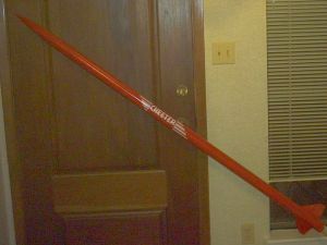
AT Cheetah stretched by 34" including 9" payload section. Motor tube extended to handle 11" motors and screw-on positive motor retention.
Modifications:
This is a fairly straight forward extension of the AT Cheetah, with extra care taken to strengthen the motor section to handle single use motors up to 11" long, particularly my favorite: the Ellis Mountain H50. I used JB Weld epoxy for any components exposed to motor heat, and Devcon 5 minute epoxy everywhere else.
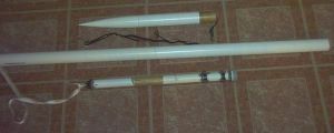
A 34" length of 1.88" tube (BMS # T-188-34) was cut off at 9" to provide body extension and payload section. Both 1.88" couplers are marked around their midpoint. One is glued to the mark into the provided Cheetah body tube, and the 25" extension glued onto that. Fold the AT elastic shock cord double into a loop and tie a knot in the ends. Run one end of the loop through the payload section screw eye, and run the other end of the long loop through the part stuck through the eye and pull it tight. The screw eye is fitted through the bulkhead and glued to the other 1.88" coupler (eye/shock cord to the inside of coupler). This coupler is then glued bulkhead first into the 9" tube up to the mark.
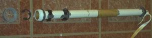
 Slide onto AT provided 12" motor tube (in order) one centering ring, both Fin-Lock assemblies, second centering ring. The AT motor hook is not used. Place "C" clip into PVC bushing cap and screw onto threaded fitting. Place this onto end of AT motor tube, pushed up until the clip stops at the motor tube, and mark the tube at the cut end of the fitting. Remove the PVC parts, spread glue on the marked end of the tube up to the mark, and push the fitting back on over the glue until it stops. If the fitting is loose on the tube, place strips of tape on the tube to make the fit tighter but do not entirely cover the end of the tube--there must be bare motor tube exposed to bond to the epoxy. Do not place glue on the inside of the PVC fitting. It will get pushed into the cap and glue the retainer together. Take care no glue gets on the removable parts or the threads. Push the aft centering ring down against the PVC fitting, using the glue pushed out by fitting on the threaded section to form a fillet. Set aside to dry.
 Construct the upper motor tube section using the 8" piece of 29mm motor tube, the AT baffle and cooling mesh, according to the kit instructions. Attach the recovery section screw eye to the baffle and tie the tubular nylon to it.
 Test fit the 2" long 29mm coupler into the lower motor section. Place it so that there is 11" to 11 1/8" of space between the coupler and the retainer "C" clip. Mark the coupler and remove it. Cover the aft half of the coupler up to the mark with epoxy and slide it into the lower motor tube only up to the mark. Smooth the glue that got pushed up by the tube onto the upper half of the coupler. Slide the upper motor tube down onto the coupler until the two motor sections meet. Make sure you do not push the coupler down into the lower motor section. This can be done by holding the lower section tightly with a pair of pliers on the top 1" (over the coupler) while twisting the upper section onto the coupler. Cut the BT-55 coupler down the side. Spread the excess glue from joining the tubes down 1" onto the aft motor section and up several inches onto the forward motor section. Add more glue if necessary. Pry open the BT-55 coupler and place it over the motor tube, 1" onto the aft motor section and the remainder on the upper section. This will strengthen the motor section joint as well as the upper part of the tube which will be subjected to hot ejection gasses. Hold the coupler tight over the motor tube with tape or rubber bands while it dries. You can remove the bushing cap and "C" clip to make sure no glue seeps into it.
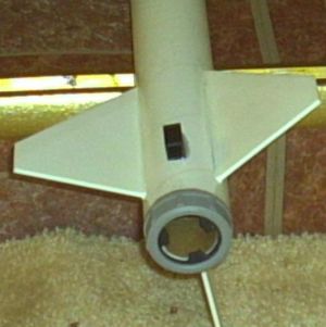
Once the motor tube assembly is dry, test fit it into the aft end of the body. Adjust the Fin-Locks to their proper placement inline with each other and directly under the ends of the fin slots. Once in place, remove the motor section and test fit the fins into the Fin-Locks. Once you're sure they fit, replace the motor tube into the body and test fit the fins through the slots.
Once you're certain all the placement is right, remove the fins carefully and extract the motor tube. Place a drop of CyA at the Fin-Lock ring/motor tube joint so they don't shift. Place a generous fillet of epoxy on both side of both Fin-Lock rings and the motor tube. Do NOT get this in the Fin-Lock channels. Wipe some of the epoxy up over the rings to form "bridges" of epoxy from the motor tube, over the rings between the fin channels, down to the tube on the other side of the ring. Slide the upper centering ring down to the forward Fin-Lock and add a fillet to the forward side of the forward centering ring.
When the motor section is completely dry, place epoxy inside the body tube where the forward centering ring will sit, taking care to keep the tubular nylon from getting epoxy on it. Push the motor section into the body all but 1". Wipe epoxy on the forward side of the aft centering ring, sufficient to drip off once placed inside and bond to the body. Slide the motor section the rest of the way into the body, aligning the Fin-Locks directly under the slots. Wipe epoxy the entire length of the bottom edge of the fin tab. This will bond into the Fin-Lock channels, to the motor tube, and will squeeze out a little while inserting which can be smoothed over the fin/body joint as a fillet. Fit the fins and set aside to dry.
Tie a small loop in the upper end of the tubular nylon. Stick a few inches of the elastic loop through the nylon loop. Push the payload section through the protruding elastic loop and pull tight until the elastic tightens a double loop on the nylon. Fit the nose cone on the payload section and the payload section onto the body, using masking tape as necessary for a good fit. If removed, replace the cap on the motor retainer. Add the lugs, or use buttons if you prefer. You are now ready for finishing.
Construction:
You need the following items:
- 1 AT Cheetah kit
- 1 34" length 1.88" diameter body tube
- 2 1.88" tube couplers
- 1 1.88" bulkhead
- 8" of 29mm motor tube
- 1 BT-55 coupler
- 2" 29mm coupler stock
- 1/8" wood screw thread screw eye
- 8' of 9/16" tubular nylon shock cord
- 1/2" to 3/4" of male threaded PVC cut from 1 1/4" pipe fitting such as pipe nipple
- 1 1.25" PVC bushing cap
- 1 1" C-clip
AeroTech recommends only CA glue and that works for most of the build. Fitting the motor section into the body requires a bit more flexibility and epoxy gives that. Also, repeated exposure of both CyA and regular epoxy to motor heat can weaken it. Thus, I recommend JB Weld for any application where heat will affect the part.
Finishing:
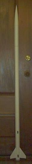
Finishing is up to the individual but I favor appliance epoxy paint. It's an incredibly tough, thick, gives a smooth finish, and requires (in fact suggests) no primer to be used. It takes a color coat well, however, anything added to an appliance epoxy paint (including a second coat of the same paint) must be added within 30 minutes or else the surface will wrinkle. As shown in the picture, I had a bit of fun with the included "Cheetah" decal.
Flight:
The motor retainer is simple to use: unscrew it, place the motor into the tube, and screw it on. I tend to lose the "C" clips, so I buy extras regularly, and I tack them to the inside of the bushing cap with a drop of CyA.
This motor section will fit any 29mm motor up to 11" length. For anything shorter you'll need a spacer. I bought a full length piece of 29mm coupler stock and cut pieces off to the proper lengths for the common motors sizes. I keep the rest around to cut as necessary for other motors. 29mm coupler stock will also serve as an adequate 29/24mm adapter. I cut two 11" sections and glued thrust rings/engine blocks inside them at 3.75" (F21) and 4.8" (F32/F72) lengths. It requires several wraps of tape to get a good gas tight seal, but tabs on the "C" clip are large enough to retain a 24mm motor with a diameter-only adapter.
Maiden flight was on an Aerotech G110-10. Perfectly straight boost, with no weathercocking or corkscrewing. Ejection was exactly at apogee, just as predicted. Came down fast due to a tangled chute, gliding tail first back and forth across the field. Just before landing it glided almost horizontal, which brought it down slowly, but fast across the ground. One fin dug into the mud as it cruised in, and broke off. Found the fin, and it was a clean break, easily repaired.
Recovery:
Suggested recovery connection is to tie a loop in the doubled elastic loop midway between the payload section and the end of the tubular nylon, and attach a chute with swivel at that point with a quick link. You will also need a heavier chute since this rocket is double the weight of the stock kit. I favor the 24" Top Flight X-form chute. Due to the recessed fins and the extra (replaceable) protection of the PVC bushing cap, faster descent rates are OK.
Summary:
Do not try to use less than an 8" extension on the motor tube. The cooling mesh needs to be stretched to 6" length to work well. Long is better for this reason, as well as for reducing the volume of the upper body tube so the ejection charge doesn't fail to pressurize it well enough.
Do not fit the motors too tightly. Due to the retainer you'll only have the nozzle to grab with pliers to extract them. With positive forward and aft retention you only need enough tape to prevent ejection gas blow-by. That is frequently no tape at all, especially with Econojet motors with their paper label. These may even require peeling off (this is due to AT's motor tube and labels but nothing to do with the retainer).
Be aware that modifications may void your kit warranty.
Related Products
 |
 |