Specifications:
Airframe:
BT-70 Length: 30 5/8"
Finished weight: 5.8oz (no motor installed)
Motor Mount: 24mm
Recommended engines: Estes D12-5 or AT RMS D9-4W
Predicted altitude: 470' on D12-5 and 620' on D9-4W
Parts List:
Torpedo:
1 - 2.5" ogive balsa nose cone, BT-70 sized (BMS semi-custom, 1"
shoulder)
1 - 1/4oz fishing weight
1 - 19 5/8" length of BT-70
1 - 7 1/32" x 7 1/4" poster board
2 - 3/16" launch lugs, 1/2" long
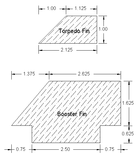
4 - Torpedo fins, 3/32" balsa
1 - 1" slice of BMS NB70-4 balsa nose block
1 - #212 screw eye
1 - 6" stainless steel fishing leader
1 - 18" parachute w/ 4" spill hole
Booster:
1 - 9" length of BT-50
1 - 1/2" length of balsa BT-50 bulkhead
1 - EB-50 engine block
3 - CR-5070, cut from 1/8" Mach-1 Balsa-Ply
1 - engine hook
1 - 2" length of TC-70 coupler
1 - 8 1/2" length of BT-70
4 - Booster fins, 1/8" balsa
(34" long BT-70 and TC-70 coupler from Totally Tubular)
Construction:
This is a fairly high-level building project. It assumes that the nose cone,
fins and body tube spirals will be filled with Elmer's Fill n Finish or
equivalent, and that the launch lug, centering ring and fin joints will all be
filleted. All construction is done with carpenter's glue, except where noted
otherwise. Fins are cut from hard balsa and streamlined. Booster fins are
mounted through-the-wall and should be laminated with copy paper for strength.
Torpedo:
Construction of the torpedo is fairly straightforward. The fishing weight is
set with epoxy into a 1.5" deep hole in the rear of the nose cone. The
nose cone is then glued into one end of the body tube. The screw eye is glued
into the center of the BT-70 nose block with CA, and the fishing leader
attached.
This assembly is glued 6" up into the aft end of the body tube, with
the leader hanging out the back. The poster board is used as a 7 1/4" long
wrap around the body tube. Trim the 7 1/32" width of the wrap if necessary
for a good fit. Use thinned white glue to glue the wrap into position so that
it is 3/8" up from the aft end of the tube.
Use plastic wrap or an ace bandage to ensure a smooth and secure
application. When dry, fill the seam. Use thin CA to harden and reinforce the
forward and aft ends of the wrap.
The torpedo fins are mounted to the wrap 90 degrees apart, with the back of
the fin flush with the back of the wrap. If desired, pinholes may be punched
into the body tube on the glue lines to make glue 'rivets'. The launch lugs are
mounted onto the wrap as well - the forward lug is set 1/2" behind the
front edge, and the rear lug is flush with the back edge. Mount the lugs on a
line halfway between two fins. This prototype was modified to add two BlackSky
Launch Rail guides, as the intended launch platform is not complete yet.
Booster Motor Mount:
The motor mount also acts as an ejection baffle and parachute compartment.
Inside the tube, the BT-50 bulkhead is glued 2 1/2" into the forward end,
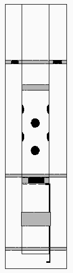
and the engine block 2 1/2" into the aft end. Then cut or drill eight
5/16" diameter holes into the center area of the tube, about 3.5" or
4" from either end. Take care not to cut too close to either the bulkhead
or the engine block, and stagger the holes so as not to excessively weaken the
tube. Soak the area around the holes and the back side of the bulkhead with CA
for burn resistance. The forward centering ring needs to be drilled with eight
5/16" holes spaced equally around the ring. It is glued to the BT-50 tube
2" from the front. The middle ring is glued so that 2.75" of the
motor tube is exposed behind it. Install the engine hook per standard
procedure, using a wrap of masking tape or other retaining device placed
1" from the end of the tube. You may want to trim the forward end of the
hook before installation to allow the use of 24-40 RMS hardware.
Body Tube:
Mark the 8 1/2" body tube at 3/4" and 3.25" from the aft end.
Cut four 1/8" slots between these lines, 90 degrees apart. Glue the
coupler halfway (1") into the forward end of the body tube. Glue the motor
mount into the body tube such that the front of the motor mount is flush with
the front of the coupler. The forward centering ring should butt against the
rear of the coupler. The aft end of the motor mount tube should wind up
recessed 1/2" into the body tube, and the mid centering ring should be
flush with the forward end of the fin slots. Make certain that the engine hook
does not line up with any of the fin slots. Test fit, trim (as necessary) and
glue the booster fins. Make certain that each fin is glued to the mid centering
ring and the motor mount tube as well as the body tube. Cut a notch 1/8" x
1/8" into the aft centering ring to allow for engine hook movement. Glue
the aft ring into the body tube, making sure that it is glued to the motor
mount tube and fin tabs as well.
Prepping for Flight: Attach the parachute to the free end of the
leader. The parachute is folded, rolled and packed into the forward end of the
motor mount tube as the two sections are plugged together. Visually align the
fins of both sections. Prep and load your motor, and you're ready to hunt
submarines!
Flight Report:
The prototype has flown 5 times now, 3 flights on D12-5s and the other 2 on
AT RMS D9-4Ws. All launches were nominal with straight boosts; all separated at
or near apogee with the booster tumbling in; all had the parachute deploy
(although on one flight it didn't open until about 20 feet AGL. Everyone
thought it was headed for a lawn dart, but the rocket gods were smiling).
On the first RMS flight (flight 3) the booster suffered a cracked fin where
the tab entered the body tube. My guess is that the empty RMS casing weighs
more than an empty D12 casing. Maybe it just landed wrong. Still, the paper
lamination held the fin together through the last two flights with no problems.
On future builds, I'm either going to make the fins from 1/8" basswood
or 3/32" aircraft ply. In either case, I'll laminate them as well. Since
total booster weight is a consideration, I'll probably go with basswood.
On every flight at least one spectator commented about the booster
separation, prompting a club member to remark, 'You should change its name to
"It's Supposed to Do That!" '
 Finishing:
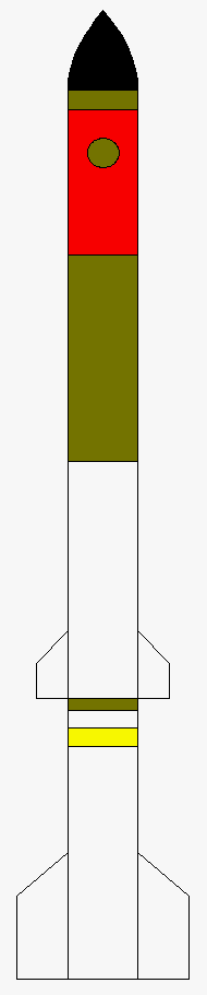
Sand and prime all surfaces. Paint the ASROC according to the figure. Colors
include gloss white, gloss black, gold, red-orange and mustard yellow.
Torpedo:
Base color is gloss white. Nose cone is gloss black; 1st band is gold,
5/8" wide; 2nd band is red-orange, 4 7/8" wide; 3rd band is gold,
6.5" wide (to top of sleeve); 4th band is gold, 3/8" wide (from rear
of sleeve to end of torpedo); the sleeve and fins remain gloss white. There are
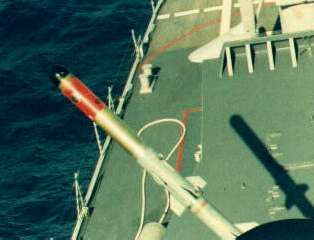
other markings on the orange-red band (such as the 1î diameter gold
circle shown), but I don't have enough data to replicate these faithfully.
Booster:
Booster and fins are gloss white. Band is mustard yellow, 9/16" wide,
9/16" from front of booster.
|