| Manufacturer: | Scratch |
Digital photos by Zhenya Olenchuke. Thanks Zhenya!
"Excuse me sir, but is that a rocket in your
pocket?"
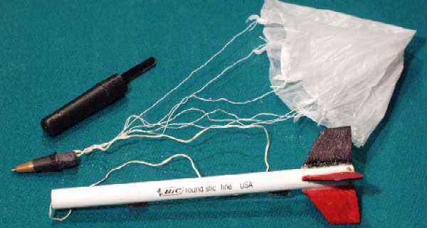
This is a fun little rocket that uses the tiny Quest MicroMaxx motors to loft a
Bic(R) pen over 50' in the air and land by Parachute.
 Design History:
I wanted to design my own MicroMaxx powered rocket but couldn't find a good
material to use for a body tube. I was just getting ready to roll my own tubes
when I noticed that the pen I was holding was about the right size. This
particular brand of pen, the Bic(R) "Round
Stic(R)" has a 5mm inner diameter, and is a perfect
fit for the MicroMaxx motors. It is a bit heavy but is very strong. As an added
bonus, the other parts of the pen supply the majority of the building materials
for the rest of the rocket.
This rocket was designed and built in one evening and flown two days later.
The fin design was just off the top of my head and seemed like a good shape for maximum strength given the thin balsa. It is similar to a WAC Corporal shape although I chose to use four fins instead of the WAC's three. Later I realized that the rocket looked a lot like the HV ARCAS sounding rocket so I renamed this design the Bic(R) ARCAS.
It's first flight was on 10/22/00 with near-perfect results and great chute deployment but the sewing-thread shock cord failed.
The next flight, with new and improved Kevlar® shock cord, was at the Blaine,
MN MASA launch on 10/28/00 with perfect launch, flight, deployment, and recovery.
Parts:
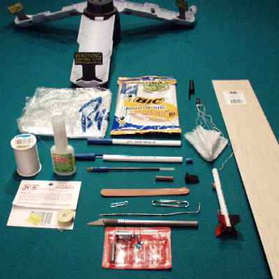
- Bic(R) "Round Stic(R)" disposable pen (for body tube, nose cone, motor thrust ring, shock cord attachment, storage cap, launch lugs)
- 1/16" balsa 1"x2.5" (fins) [Can substitute cardboard from back of paper tablet]
- Sewing thread (for parachute shroud lines)
- Plastic bag from grocery store vegetable isle (parachute)
- Small paper clip (motor retainer pin)
- 18" Kevlar® thread (for shock cord)
Tools/Supplies:
- Large paper clip, opened up or other 8" piece of stiff wire or 1/8" wood dowel
- Razor knife
- Pocket knife
- Scissors
- CA glue, medium (Zap-A-Gap)
- Spent Quest MicroMaxx motor
- Facial tissue (i.e. Kleenex)
- Fingernail file or sand paper
- Small piece of wax paper
- Wire cutter (able to cut a normal paper clip)
- 1/16" drill bit (optional if have sharp pointed Xacto knife)
1. Disassemble
pen:
a. Twist off tip w/attached ink tube (might need pliars)
b. Carefully use fingernails or pocket knife to extract end plug
(If it won't come off, push it out with a stiff wire from the other end, or, in
stubborn cases,
cut off the last 1/8" of white tube and the end plug will come with it.)
This will be used in step 5 to construct the motor thrust ring and shock cord
attachment point.
c. Separate beige ball tip w/attached ink tube from the colored cone-shaped
grip
2. Nose cone:
a. Shorten the shoulder of the conical grip so that only 3/8" of shoulder
remains
(this will give more room for the chute and make the nose cone eject more
easily).
Cut it using a sharp razor knife by rolling the cone under the knife against a
table top (protected by cardboard!).
Save the remaining ring for use as the motor thrust ring in step 5 if the end
plug was not salvagable from step 1.
b. Note: this step can be messy: Cut off the ink tube from the tip, leaving
about 1/4" so the pen still has some ink left to write with.
(Yes, this will remain a functional pen to use for filling out your flight
cards!)
c. Plug end of ink tube that is still attached to the tip with a spike of
tissue and soak the tissue with CA glue.
Spray it with CA accellerator/kicker if you have some. This should keep it from
leaking.
d. Cut off and save the clear part of the remaining ink tube and carefully
discard the ink-filled portion.
e. Drill small 1/16" hole in middle of shoulder of cone using knife tip or
drill bit.
f. Carve small groove from hole to end of shoulder so shock cord will not be
pinched.
g. File or sand shoulder of cone until it EASILY slides in and out of body tube
h. Reinstall the pen tip into the grip.
3. Mark body tube for fins and launch lugs:
a. Mark the fin alignment lines on the body tube.
1. Hold the pen so you are looking at the aft end. Use a pencil to mark
three equally spaced 120 degree marks on the end edge of the body tube.
2. Lay the tube on a flat table, lay a pencil on the table perpendicular to the
body tube.
3. Rotate the body tube until an alignment mark lines up with the pencil tip
4. Slide the pencil on along the aft 2" of the body tube to make the fin
alignment line.
5. Rotate the body tube 120deg and make another line. repeat for 3rd fin.
b. Using the same technique, mark the launch lug attachment point line on the
body
tube between two fin lines. this line should extend from the aft end of the
tube to a bit forward of the mid-point.
4. Build motor retainer clip:
a. Use tip of razor knife, or small drill bit to make two 1/32" holes each
1/16"
from the aft end of the body tube and spaced 90 degrees apart, on opposite
sides of a fin line, opposite of launch lug.
b. Cut a 3/4" piece of normal paper clip wire, bend the last 1/4" up
into an L shape
c. Holding the clip by the short leg of the L, insert the long leg through the
two
holes. It may take some wiggling to get the holes angled so the clip will
pass between them. The fit should be firm enough so that the clip will not
fall out on its own, yet can be inserted and removed fairly easily.
d. Make sure the wire is far enough off to the side so it will not cross the
nozzel
area of the motor. If it is too close, try again on another part of the tube.
The wire only needs to cover a small area of the motor in order to prevent the
ejection charge from blowing the motor out of the rocket.
e. Remove retainer wire for next step.
5. Build and install motor thrust ring/shock cord attachment ring:
a. Cut a 1/4" cylindrical section from the pen end plug, discard flat part
of the plug.
(If unable to get a good piece, use the remainder cut from the nose cone in
step 2)
b. Make 1/16" hole in side of ring
c. Make small groove from hole to one edge of ring
d. Insert Kevlar® thread into hole and tie securely (bowline or square knott)
leaving
a 1/4" loop so the knot will not interfere with fit of ring.
e. Insert ring into forward end of body tube and push all the way down (using
unbent large
paper clip or long dowel) until it is approx 1/2" from AFT end of body
tube.
f. Insert spent motor into aft end of tube and push against a flat table, then
with
a tool or another spent motor until engine is recessed 1/8" from aft end
of
body just clearing the motor retainer clip holes.
g. Insert motor retainer clip
h. Use wire or dowel inserted through top of tube to push motor retainer ring
to
check that it is firmly against motor so that motor is lightly pusing on motor
retainer clip. Due to the tight friction fit, it should not be necessary to
glue the ring in place.
i. Remove motor retainer clip and use wire to push the spent motor out of the
body,
without disturbing the thrust ring, then replace the clip.
6. Launch lugs:
a. Cut two 1/4" pieces from the clear part of the ink tube saved from step
2d.
b. Make launch lug stand-offs from balsa. Approx 1/8" wide by 1/4"
long. These
are necessary so the rocket motor will be centered over the ignitor on the
MicroMaxx launch pad. Some experimentation may be necessary to get the correct
stand-off width.
c. Sand a stripe down the side of each launch lug tube to help adhesive to
stick
d. Use CA glue to glue the balsa standoffs to the tubes. lay on a piece of
wax-paper on a flat table so lug will stay parallel with stand-off. Try not
to get CA on your fingers.
e. Sand two 1/4" long stripe segments of the launch lug alignment line on
the side
of the pen tube. One at the mid point, and one 1/2" up from the aft end.
f. Use CA glue to glue lugs/standoffs to body tube. After 30 seconds, try
sliding the MicroMaxx
launch rod through the lugs to verify alignment. If they are not straight, just
break one off
and try again.
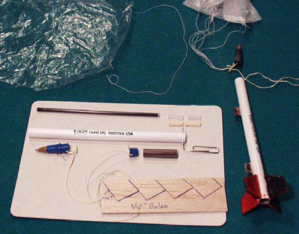
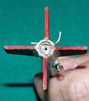
7. Fins:
a. Make fin pattern: 7/8" long at root, 5/8" along the trailing edge,
and 1/2" at tip. Use pattern to
layout fins on 1/16" thick balsa (or cardboard) sheet per above photo.
Wood grain should
be parallel with the swept leading edge of the fin for maximum strength.
b. Cut out fins with a razor knife. Sand leading, trailing, and outboard edges
to a
rounded or pointed shape. Sand root edges flat.
c. Sand body tube adjacent to fin alignment lines so CA glue will stick
d. Apply CA to one fin root edge and press to body tube so trailing edge is
even
with end of tube (use alignment mark on end of tube and alignment line
extending
up body to ensure alignment. Hold for 20 seconds for CA to set. Wait for a
minute or two before proceding to the other fins.
e. After all fins are applied, add fin fillets with epoxy or CA glue mixed with
baking powder or aluminum oxide powder. I just used medium CA and sprayed
some accellerator to make an acceptable fillet.
f. Magic markers work great for "painting" the balsa fins. Paint
alternating colors
on opposite sides of the fins so you can check if the rocket spins during climb
(it shouldn't if the fins are straight). Note: CA Accellerator will make the
marker ink run.
8. Parachute:
a. Cut 5" diameter hexagonal chute pattern from paper and tape to plastic
bag
material. An alternate method is to fold a piece of plastic in half, then in
thirds and make one cut 2.5" from apex.
b. Cut out chute
c. Cut 3 three 12" shroud lines from strong thread
d. Attach shroud lines to chute. Theory: tape would be too stiff for such a
small chute so I just tie the line directly to the corners of the plastic.
This has an unintended benefit of causing the chute to be more hemi-spherical
when open.
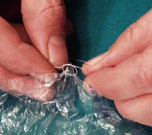
1. tie a slipknott (or even simple overhand) close to end of shroud line
2. pinching a corner of the chute to make a little 1/4" spike
3. slide slip knott over spike and pull tight (if used an overhand knott in
step 1, then
tie a second overhand to form a square knott)
4. attach other end of shroud line to adjacent corner using same method.
5. repeat for other two lines
e. Put finger through the three shroud line loops and pull on the apex of
the chute
so all lines are taught and straight. Then tie an overhand knott in the
end of the combined shroud lines to form a 1/2" loop.
f. Tie shock cord to nose cone using bowline or square knott leaving 1/2"
diameter
loop so knott does not get pinched along side of nosecone and to provide a
mounting location for the chute
g. Attach chute to shock cord by feeding the shroud line loop through the
shockcord/nosecone attachment loop, then feed the chute through its own shroud
line loop, gently pull tight while ensuring all lines are straight.
Stability testing:
Before launching this rocket, make sure that it will be stable so it doesn't
fly into people.
This design has been well tested and if the instructions are followed exactly
it will be stable.
Here's the process to check stability if you've made any alterations to the
design, or just to be sure:
1. Load engine and pack chute according to "Preparation for Launch"
instructions below
2. Find the Center of Gravity (cg) point of the rocket by balancing it on a
pencil or
other thin object. Mark this point on the body tube with a pencil.
3. Tie a 6' piece of string to the rocket at the cg point and secure it with a
piece
of tape.
4. Twirl the string and rocket over your head and verify that it flies
"pointy end
first". Purposely try to start swinging with the rocket pointed backwards
or
sideways and verify that it quickly rotates to a nose-first attitude.
5. If the rocket is not stable, it will require larger fins, or fins angled
further
aft. There is not a convinient way to add nose weight to this type of design.
(although you could try making a nosecone from the pen cap, which would add
weight to the nose but hurt performance.
Preparation for Launch:
1. Load engine
a. Remove engine retainer clip
b. Install MicroMaxx motor (verifying it is nozel end down), until recessed
past retainer clip holes.
c. Reinstall engine retainer clip
2. Insert recovery protection wadding. two pea-sized balls of cellulose or
Estes
tissue. Use straightened large paper clip as a ram-rod but do not push all the
way into the motor, just until wadding contacts motor thrust ring.
3. Pack chute (Note: do this immediately prior to launch. A chute packed
for several
hours may not open as reliably):
Theory: It is very difficult to pack a large chute into a small tube and have
it
open reliably. The technique used here depends on the chute being constructed
of
a material that will not stick to itself when tightly compressed (which most
plastics do). Another problem can arise with a very lightweight rocket not
developing enough descent rate to cause the chute to inflate. This packing
technique uses the force of the ejection (which is disproportionately strong
for
MicroMaxx motors) to blow the nosecone, shock cord, and shoud lines out first
so
they are stretched out. The canopy is then blasted out mouth- first so it is
forcefully inflated as it exits the body tube. This technique has worked
flawlessly,
resulting in instant openings.
a. Talc both sides of chute
b. "Flake" (the skydiving term) individual pannels of chute so it is
stretched out
with all lines taut in center and the material neatly arranged.
c. Fold peak 1" of chute back on itself so the chute will be short enough
to fit
the body tube.
d. While keeping taut, gently sqeeze sides of chute into a thin cylinder shape.
Do not fold or roll, just sqeeze.
e. Insert part of shock cord into tube, leaving enough outside so it is even
with
the chute lines and chute.
f. Insert chute into tube, apex/peak first, gently sliding it in. Do not force
or
cause chute to kink. Periodically tug on the lines to ensure that the chute
is able to slide back out easily.
g. Insert a pea sized bit of wadding and use straightened paperclip to push
chute
down far enough to leave room for lines and nose cone.
h. Make 3/4" S-folds in the lines and shock cord together between thumb
and finger,
then slide into tube. Insert a small piece of wadding to keep them from falling
out. This is difficult, especially since Kevlar® shock cord is springy.
i. Insert nose cone, making sure to keep from pinching lines. Check that
nosecone
easily slides back out.
j. Install cap on pen to hold nosecone in place until ready to launch. (cap
will be
removed once rocket is positioned on the pad)
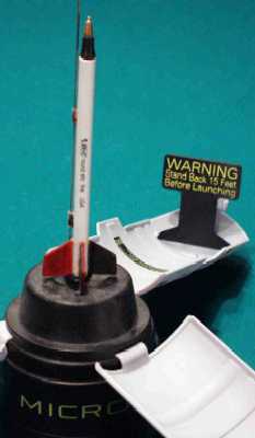
4. Place rocket on pad:
a. Ensure that safety key is removed from launch controller and install new
ignitor on MicroMaxx pad.
b. Place over launch rod on MicroMaxx pad.
c. Remove pen cap
d. Ensure that ignitor slides up into engine nozel without contacting the motor
retainer clip, which could short out the ignitor
5. Launch
a. Check that area is clear of people/pets
b. Insert launch key, check for audible continuity tone
c. 5 4 3 2 1 Launch
d. Rocket will climb about 50-100' then eject the nosecone and parachute.
Because
of the way the chute is packed, it should open immediately during the ejection
process.
e. Recover the rocket. Note, the engine and retainer clip may be hot.
f. After allowing 1 minute to cool, remove the engine retainer clip and insert
the staightened paper clip from the top end to push the spent motor casing out
of the rocket.
6. Store:
a. Store rocket with chute unpacked and spent motor removed
b. Clean any exhaust or ejection residue from the inside of the body tube using
a
Q-tip and rubbing alcohol.
c. Wrap the rocket and chute up in a paper towel and store inside of a section
of
cardboard paper towel tube or small box.
Build more with different designs. Make sure to test them for stability using the twirling method before launching a new design.
Future Plans:
This project was so successful that I plan to develop other designs around this
concept.
1. Bic(R) Corporal
2. Bic(R) Mercury Redstone
3. Bic(R) Saturn IB (with clustered motors)
4. Bic(R) Saturn V (with clustered motors)
5. Bic(R) Ariane (with drop-off boosters)
"Bic" and "Round Stic" are registered trademarks of the MM Bic Corporation, Milford, CT. Bic Corporation does not own or market these rockets, their name is used purely to accent the source of some of the rocket's components.
Designs copyright (c) 2000 by Jeffrey P. Hove, all rights reserved. Non-commercial use granted provided credit is given and this web page is linked to any on-line display of rockets derived from these techniques. I reserve exclusive rights to negotiate with Bic Corporation regarding advertising use of the Bic rocket idea.
 |
 |