| Manufacturer: | Scratch |
Bucky II
by Dennis McClain-Furmanski
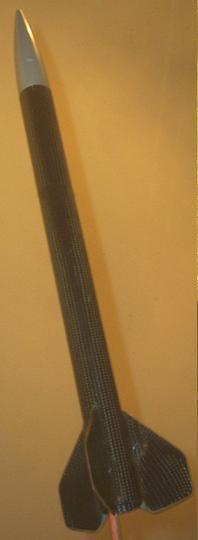 This carbon composite 29mm
minimum diameter rocket is the second of three versions intended for NAR
mid-power altitude competition events. Specifically, this version is ito be
used to break the NAR class C (adult) G power altitude record (1140 m =
3740’).
This carbon composite 29mm
minimum diameter rocket is the second of three versions intended for NAR
mid-power altitude competition events. Specifically, this version is ito be
used to break the NAR class C (adult) G power altitude record (1140 m =
3740’).
The name is derived from "buckytube", the name for the axially symmetric fullerene carbon compounds named for Buckminster Fuller. Although the design continues to be refined and other variations built, this model, with a payload section, has been the most successful so far.
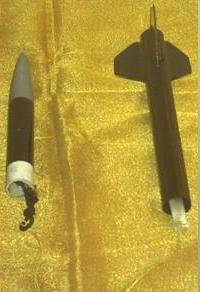
Dimensions
- Weight (flight prepped, without motor): 4.9 ounces
- Length: 19.75"
- Body section lengths
- Main: 10.75"
- Payload: 4.25"
- Diameter
- Inner: 1.18"
- Outer: 1.21"
- Nose length: 4.25"
- Fins
- Root: 3"
- Semi-span: 1.75"
- Tip: 1.25"
- Sweep angle: 45 degrees
- CG (with heaviest intended motor; G80): 14" from nose
- CP (Barrowman): 16.4" from nose
- cD (subsonic; AeroDRAG): 0.379
Parts
- Body: 15" of single layer carbon composite tube molded over a 29mm coupler stock mandrel
- Fins: 1/16" 3-ply birch laminated with carbon composite
- Launch lug (1/4"): carbon composite molded over ¼" steel launch rod
- 4" of heavy paper 29mm coupler, cut as 3" plus two ½" pieces
- Apogee part #19114 styrene nose cone
- 4’ braided 150 lbs. test Kevlar cord
- 6" of ¼" Kevlar wrapped elastic cord
- 1’ of 5/16" tubular nylon
- 1.125" diameter ¼" plywood bulkhead
- ¼" screw eye
- Appx. 1 cubic inch of copper mesh from pot scourer
- 12" red Mylar parachute kit
Lamination was done with 2" nominal diameter seamless carbon sleeve from Aerosleeve and Epoxy Products Premium Number 2 no-blush epoxy, coated with urethane and finished with acrylic. Construction was done with Loctite 90 minute epoxy.
Main body: The tube was laminated similar to the instructions in the tutorial available on the Aerosleeve web site. After laminating and finishing the tube, it was cut to size. The copper mesh (about ¼ of a copper pot scrubbing pad was inserted. One of the ½" pieces of coupler was epoxied 4.5" into one end as a motor block. The Kevlar thread was doubled and tied into a loop, and wrapped around the other ½" piece of coupler as a shock cord anchor, and this was epoxied 4.5" in from the other end, the copper mesh now trapped between the two pieces. The tubular nylon was slid over the Kevlar thread down to the anchor, to act as an anti-zipper mechanism.
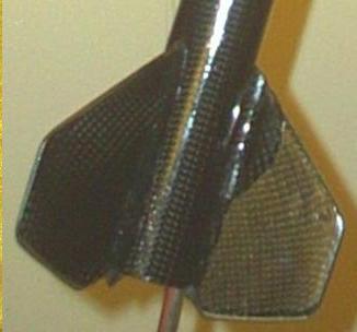 Fins: The fins were cut from plywood
stock and sanded to a wedge on all edges except the root. These were then
inserted into 4" pieces of carbon sleeve, which was pulled tight to fit
the edges, and laminated using weight press. When dry, the fins were trimmed,
the edges resanded to an edge, except the root which was sanded flat, and
finished.
Fins: The fins were cut from plywood
stock and sanded to a wedge on all edges except the root. These were then
inserted into 4" pieces of carbon sleeve, which was pulled tight to fit
the edges, and laminated using weight press. When dry, the fins were trimmed,
the edges resanded to an edge, except the root which was sanded flat, and
finished.
Fin/body construction: The body was marked for fin placement (120 degrees apart, root/trailing edge corner at the aft end), and the body and fins prepared for epoxying. The fin placement areas were sanded to remove the finish down to the carbon fiber. A 1/16" drill was then used to drill pits into the tube (but not through) every ¼" along the marked fin line, as well as 1/8" to either side of the line. The fins were drilled similarly 1/8" from the root edge, through the carbon fiber, to the wood, and the surface sanded down to the carbon between these pits and the root edge. The fins were then epoxied to the body along the lines. Once dry, fillets were added to cover the pits drilled on both body and fins. Three 1/16" air vent holes were drilled through the body 120 degrees apart, between the lines of the fins, 2" aft of the forward end.
 Payload section: The bulkhead was
drilled and the screw eye inserted and turned tight. Epoxy was added to cover
the center of the bulkhead on the eye side, and run through the eye itself to
keep it tight. A 1" loop was tied in one end of the elastic cord, and the
other end was tied to the screw eye. The bulkhead was then glued to the 3"
piece of coupler with the eye and elastic run down through the coupler. When
dry, this was glued bulkhead first 1.5" into the payload section, and
fillets added to the bottom side of the bulkhead/coupler joint. Three vent
holes were drilled through the payload tube halfway between forward and aft
ends.
Payload section: The bulkhead was
drilled and the screw eye inserted and turned tight. Epoxy was added to cover
the center of the bulkhead on the eye side, and run through the eye itself to
keep it tight. A 1" loop was tied in one end of the elastic cord, and the
other end was tied to the screw eye. The bulkhead was then glued to the 3"
piece of coupler with the eye and elastic run down through the coupler. When
dry, this was glued bulkhead first 1.5" into the payload section, and
fillets added to the bottom side of the bulkhead/coupler joint. Three vent
holes were drilled through the payload tube halfway between forward and aft
ends.
Completion: A launch lug was laminated and finished similar to the tube, using a ¼" launch rod for a mandrel. This was cut to 2" length, and the ends cut at a 45 degree angle. Holes were drilled into one of the fin fillets from the leading edge to 2" aft, and the launch lug epoxied over these. Fillets were then added to the fin/lug joints. The Kevlar cord was tied through the loop in the elastic with a slip knot. The nose cone was sanded with fine grit, washed with soap and water, painted first with white appliance epoxy paint, then aluminum paint, then a coat of acrylic. This was inserted into the forward end of the payload section, and tested for fit, with masking tape being added as necessary to get a tight seal. The entire rocket was then recoated completely with another layer of acrylic for an even finish.
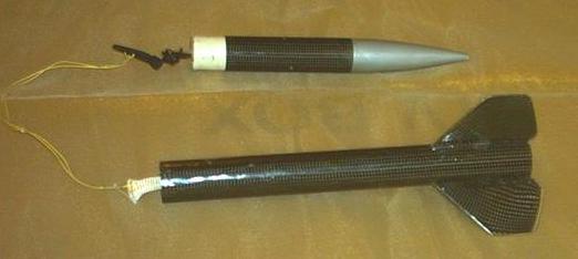
Flight prep: A circular streamer was constructed by running Kevlar shroud line cord through a hole in the center of a 12" red Mylar parachute. It was tied and taped in place on the Mylar, and a snap swivel tied to the other end. This was snapped onto the loop in the elastic cord, and the cord and cute packed into the rocket. The complete rocket was then weighed. CD calculations and flight predictions were run using AeroDRAG. Predictions showed the need for very long tracking/ejection delays to prevent high speed ejection. Results with some motors with adequate delay (at local elevation of 600’, air temp 59 degrees, adjusting for weights as given by NAR testing) were:
Mfgr/Motor Altitude Deployment speed
- Estes E9-8 1420’ -16 fps
- Apogee E6-8 2286’ +11 fps
- AT F32-15 5107’ -63 fps
- AT G25-15 7543’ -34 fps
Flight tests: Estes E9-8s were selected for initial testing. Masking tape was used to friction-fit the motor in into a 29/24mm adapter, and to fit the adapter into the rocket. The tests were flown in moderate (5-10 MPH) winds. Boosts were perfectly vertical with no tipping or weather cocking. On the first flight the altitude appeared greater than expected, estimated at 2000’. Ejection occurred prior to apogee, contrary to the simulation. This was at first taken to be a slight motor malfunction producing an early ejection. However, the second flight displayed the same characteristics: altitude appeared greater than predicted and ejection was before apogee. Together these are taken as evidence that the rocket was outperforming the predictions. In both cases recovery was nominal, the circular chute/streamer slowing it adequately and being well visible from the time of ejection. No burning was evident, indicating that the copper mesh protected the Mylar sufficiently.
Conclusion: Bucky II appears to perform better than expected. The construction is very tough and able to withstand relatively high speed landings. The home made ejection baffle works well. The only problem with its performance is finding motors with suitable delays – the G motors with adequate delays are not commonly available. An altimeter has been obtained for use in accurate testing to verify whether the rocket performs as well as, if not better than, the predictions made from the design. A second build of this design will be done to attempt to replicate the results.
 |
 |