| Manufacturer: | Scratch |
(Contributed - by Bob Fortune)
A while back I realized I had a bunch of odd sized 54 mm motor mount tube (mmt) kicking around. The inside diameter was off a bit and would not fit LOC adapters so it sat in my tube box. Also taking up space was a sheet of copper foil clad G10 that electronics folks use to make printed circuit boards. You can find the type of copper clad G10 I used at Radio Shack, Fry's or a well stocked electronics supply place. The foil is only a couple of mils thick and is meant to be etched away in the circuit making process. The only thing I was lacking was a nose cone (NC) that I picked up at the hobby shop that fit 54 mm mmt.
I was set, all I had to was figure out a design. I wanted to cut the fins from the G10 with the minimum of fuss which explains their triangular shape.... just draw diagonals and cut. I had one piece of 32" 54mm mmt and one piece of 17" 54mm mmt that I wanted to get rid of hence the length of the rocket. Plugging these parameters into RockSim (www.apogeerockets.com) made for a surprisingly stable rocket able to fly on all the motors from E to H in 29mm without adding nose weight.
So I had an odd rocket that was a bit boring except for the interesting brushed copper fins. Then I found a long fiberglass rod in the garage that would make a nifty "probe". This was originally made to hold a flag on a long pole you would attach to a bicycle for visibility. I modeled this in RockSim and it still flew well but the rod was a bit splintery so I looked around the garage and came up with something a bit more robust, GlasSpar. GlasSpar is a fiberglass tube, black in color that comes in 3 foot lengths. It can be found at hobby shops and is used as a central spar in model airplane wings.
The nose cone is hacked off at the tip until the hole that is exposed matches the O.D. of the GlasSpar. I used a bench grinder to accomplish this task. Allow about an inch to protrude out the aft end of the NC which is also cut to the same GlasSpar O.D. These holes will act as centering rings for the probe. Wrap masking tape around the protruding aft end of the GlasSpar to keep it from moving forward. Glue consecutive loops of string where the GlasSpar exits the NC forward building up the string till it matches the ogive of the NC using thin CA to keep the string in place. Epoxy this mess smooth to match the NC. Make sure that this probe is removable (just in case) by putting a piece of wax paper or plastic wrap between the NC and string. The masking tape alone will keep the probe from exiting the NC on deployment but just in case I epoxied a knife insert into the GlasSpar to hold a screw. I had to grind most of the threads off the outside of the insert to get it to fit properly. A knife insert is like a metal coupler that has knife-like wood screw threads on the outside and machine screw threads on the inside and is usually made of brass. Two holes are drilled in the NC shoulder through which 1/16" cable is passed to make a loop secured by crimps. A piece of metal drilled with two holes or a master link keeper off a bike chain is screwed to the knife insert. The forward bridle quicklink connects the master link keeper and NC cable together to make a redundant NC retention system. A couple of screws through the airframe into the NC makes for a real belt and suspenders approach to bridle retention. This rocket has deployed at over 100 mph with no ill affects.
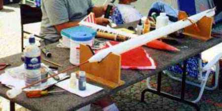
Now I've got this long rocket with an equally long proboscis and what am I going to call it. The probe made me think of the sticks we used roasting marshmallows over the campfire at the last scout campout and I dashed into the house to find a couple of the tasty treats. Installing them onto the GlasSpar I knew what to call this thing......... the "Cub Scout".
The fins are mounted about 3/4" from the aft end. I used a dremel with a fiberglas-covered cutoff blade to cut slots in the body tube (BT) once I had epoxied the LOC adapter in place. If you use plywood you can stack blades together to make a "stacked Dado cutter". Two larger blades on the outside and 3 or 4 blades sandwiched in between make a nice slot for 1/8" plywood for your future rocket projects. I made sure that the centering rings were located in the LOC 54mm-29mm adapter so that slots could be cut to receive the fins, actually locking them in place.
Since the fins are copper-clad and tarnish rapidly I took some 100 grit sandpaper and made a nice "brushed" finish in one direction both sides and sealed them with clear shellac. Spray varnish, lacquer, or acrylic will work as well. Once dry they were epoxied into place taking care to make the fillets as smooth and straight as possible since they would be exposed and left unpainted. Microballoons and epoxy blended together make for nice fillets which can be smoothed with a gloved fingertip dipped in denatured alcohol. Let the epoxy set until it is not goopy but will still move easily under finger pressure. Take care to wipe the epoxy off in a straight line where the fillet remains exposed at the fin.
The retention system is Stu Barrett's Anti-Zipper method. You can see the details of this construction at: Rocketry Online Info Central click on the Anti-Zipper Design. This is a great system and I heartily recommend it where ever possible. It even works well for smaller rockets! The baffle assembly is a LOC bulkhead assembly with an extra bulkhead cut in half and inserted in coupler as shown. You might also use a second bulkhead and drill holes that do not line up with the forward bulkhead as the aft baffle in lieu of the system I described. Discard the LOC supplied eye screw and substitute an eyebolt which is double nutted behind the bulkhead to prevent unscrewing under the parachute. This eyebolt can spin freely on the washers to allow the booster to rotate as it descends without taking a chance on having it unscrew the bolt.
![]() The spiffiest
part, I think, is the motor retention system. It is a variation (read: blatant
rip-off) of Don Qualls UMRS though it does not use the PVC cap Don originally
included in his design. You can find the UMRS in an earlier issue of Sport
Rocketry. In 1 1/2" PVC, the cap was too heavy for this application. This
whole assembly is serendipitous for I forgot to add T-nuts before assembling
the adapter. Then the knife inserts, which I had intended to retrofit after the
fact, broke in the hard epoxy. Egads, what to do. Scrounging through my
plumbing parts I came up with an ordinary 1 1/2" PVC nipple and a 1
1/2" PVC collar that is used to hold a nylon gasket and P-trap assembly
into the wall for your sink drain. These items are available at the hardware
store. I cut the nipple off at a length that allowed the thrust ring on 29mm
AeroTech RMS to be retained by a centering ring (CR), so to speak, of G10 and
the PVC collar. It's actually a retention ring in this usage. Sand and test to
fit before epoxying this into place. Make sure you have at least 3 or four
threads of the collar on the nipple for positive retention. Test fit the nipple
for length before epoxying in place to make sure it fits all the 29mm SU and
RMS cases possible.
The spiffiest
part, I think, is the motor retention system. It is a variation (read: blatant
rip-off) of Don Qualls UMRS though it does not use the PVC cap Don originally
included in his design. You can find the UMRS in an earlier issue of Sport
Rocketry. In 1 1/2" PVC, the cap was too heavy for this application. This
whole assembly is serendipitous for I forgot to add T-nuts before assembling
the adapter. Then the knife inserts, which I had intended to retrofit after the
fact, broke in the hard epoxy. Egads, what to do. Scrounging through my
plumbing parts I came up with an ordinary 1 1/2" PVC nipple and a 1
1/2" PVC collar that is used to hold a nylon gasket and P-trap assembly
into the wall for your sink drain. These items are available at the hardware
store. I cut the nipple off at a length that allowed the thrust ring on 29mm
AeroTech RMS to be retained by a centering ring (CR), so to speak, of G10 and
the PVC collar. It's actually a retention ring in this usage. Sand and test to
fit before epoxying this into place. Make sure you have at least 3 or four
threads of the collar on the nipple for positive retention. Test fit the nipple
for length before epoxying in place to make sure it fits all the 29mm SU and
RMS cases possible.
The G10 retention ring is made of a scrap of the same material as the fins. Old circuit board will work just as well here though you may want to pick up some additional boards while at the electronic shop. Make a square on the material you intend to cut just a bit larger than the collar I.D. Draw diagonals to give a center reference point. Determine the I.D. of the coupler and divide by two to give the radius and mark this on the G10. Do the same thing with the motor nozzle and mark the radius as well. Using a compass draw a complete circle and then cut out best way possible. I have circle cutters and hole cutters which makes the job easy on a drill press but sawing, sanding and judicious use of a Dremel will work just as quickly.
The bridle is 15 feet long with quick links on either end and a welded ring as the parachute attachment point. I threaded 15 feet of 1/4" nylon "shoelace" through 4 feet of 1/2" "toooobular nylon". The 1/2" tooooobular stuff acts as an ejection gas protector for the smaller diameter nylon bridle and is covered with tape at the booster attachment point quicklink to protect the smaller nylon knot. This material can be found at R.E.I or any other mountaineering store or on the net. I used a 42" parachute with a reefing line though a 36" round nylon chute should work just fine. It has recovered twice from 1,500 feet with no damage with only the deployed bridle slowing its descent, the parachute chose to remain asleep in the airframe. : ) Attach the parachute to the bridle so that the booster hits the ground first but also take care that the bridle is long enough to pull the chute free of the upper BT since the suspension lines on the chute can often be quite long.
Parts List:1 32" 54 mm (2.14") motor mount tube $5.65
Going over this I realized there are over $40 worth of parts here which may be too much for some folks. You may be able to substitute 3/32" plywood for the G10 and save 5 bucks. You can also eliminate the use of the LOC MMA-3 using only centering rings and a motor mount tube and knock off another couple of bucks as well but for strength I would then choose to go to the motor mount tube with the fins. Changing the retention system to something a little more konventional might also save a dollar and trip to the hardware store.
1 17" 54 mm (2.14") motor mount tube $2.83
1 ea. LOC Bulkhead Assembly BA-2.14 $3.00 (includes coupler and eye screw)
1 ea. Bulkhead to fit coupler (make this)
1 ea. LOC Nose Cone PNC 2.14 $8.50
1 ea. LOC 54mm-29mm adapter MMA-3 $4.75
1 36" GlasSpar fiberglass tube x 3/8" diam $3.25
1 ea. G10 sheet 8" x 8" copper clad 2 sides $7.35
1 ea. eyebolt
2 ea. washers
1 ea. piece o' metal (master link clip) $0.65
2 ea. nuts
1 15' 1/4" nylon "shoelace" as bridle $0.13 per foot
1 4' 1/2" toooobular nylon as sheath $0.24 per foot
2 ea. QuickLinks $2.25 ea.
1 ea. 3/4" Welded Ring $0.49
1 ea. welded ring - chute attachment point $0.45
1 3/4" 1 1/2" schedule 40 PVC nipple (cut off) $0.14
1 ea. 1 1/2" PVC collar $0.65
1 ea. G10 collar centering ring/retainer (priceless)
1 ea. door stop bumper (steal from home)
2 ea. Marshmallows (Stay Puft) (pantry item)
I would recommend the first flight to be done on an F motor without the probe in place just to make sure everything is working okay. Put a piece of tape over the NC hole if you fly it without the proboscis. AT Econojet G35's fly this quite nice though I recommend a 4 second delay if marshmallows are installed, the 7 is a bit dicey. I have also flown it successfully on AT RMS G64 with a 7 second delay.
If you have any questions or comments please email me! bob@fortunenet.com
Thanks for taking a look at my design..........................Bob Fortune

 |
 |