| Manufacturer: | Scratch |
The Cutlass was inspired by the Star Fury fighters from the Babylon 5 Sci-Fi series. I liked the look of the Star Fury, with the engines out on the end of the "wings". I also found a use for those paper tubes that come with the Copper head ignitors. I was also pretty happy with the way the cockpit canopy turned out.
Main fuselage parts list:
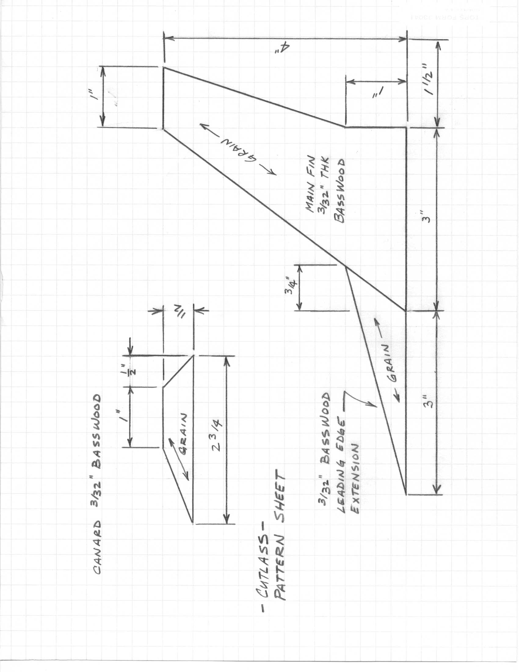
Engine pod parts list: The Cutlass started out with a shorter 9-inch body tube, but it soon became apparent that I would need an unacceptable amount of nose weight. I added another 9-inch section of tube so the final model would use a stock section of Estes BT60. The motor mount is pretty standard modroc construction. I used a length of Apogee light Kevlar® attached to the end of the motor mount tube and tied off with a loop at the open end of the body tube. I used an engine hook made of .035 inch music wire. I bent the hook long enough so the forward bend would catch the forward end of the motor block. This lets the motor block absorb any ejection force rather than the thin wall of the body tube. I had to add split shot sinkers to the nose cone, but initially I was guessing at where the CP would probably be. I dropped split shot into the tip of the cone and secured them with hot melt. I have the CG with a C6-3 motor and flight ready at approximately 7 inches from the rear of the model. In the end the Cutlass came out way heavier than I figured on. (I could have used balsa on this model but I have been using basswood more often for modroc construction.) Without paint or motor it weighed in at 145 grams. This is a bit beyond the recommended maximum lift off weight of C motors. I launched it for the first time on a C6-3. It boosted nice and straight with apogee around 150 feet. Ejection occurred about 1 second past apogee. I launched it again on a C5-3 with similar results. I will either rebuild this model with a 24mm motor mount or restrict it to 18mm D's. Though the flights on the C6 and C5 were safe enough, I would restrict flying it on these motors to calm days. I would not build this again with the 18mm mount, so the parts list included is for use with a 24mm mount. The basic construction would remain the same except for this change.
Engine pod construction: Mark each engine pod tube in 3 places at 120 degrees apart. One mark will be for alignment of the wing joint the other two for the bass wood strips. Glue the basswood strips onto the rear of the engine pod tube. Mark the front of the engine pod tube 1/2 inch from the end. Trim the tube coupler into the 4 1/2" long sections and the Copper Head tubes into 28, 1" long sections. Cluster up the Copper Head tubes into 7 bundles each and glue into the 1/2" sections of tube couplers so 1/2" is exposed. These are the engine pod nozzles. Glue the "nozzles" into one end of each engine pod tube so the coupler tube is flush with the end of the BT20. Glue one wire nut into each CR5-20 so the base end of the wire nut is flush with the edge of the centering ring. I used CA for this. Glue these "intakes" into the other end of the engine pod tubes so the front edge of the centering ring is 1/4" into the tube.
Main fuselage construction: Mark the body tube for the main wings; launch lugs and the fairings using the marking guide. Glue up the wing parts. I didn't streamline the wing edges; I just rounded them off a bit after they were all glued up. Be sure to keep the root end and the engine pod root ends parallel. Glue the root fairings on each root end and round off the front edges. I glued the engine pods to the wings before I glued the wings to the body tube. The pod root of the wing is set at the mark made 1/2 inch from the forward end of the pod tube. The rear edge of the wing is flush with the rear of the body tube. The 3-inch launch lug is glued to the 3 inch x 1/8-inch square strip and glued to the rear end of the body tube. The 1-inch lug with the 1-inch 1/8-inch strip is glued 12 inch from the rear, measured to the front end of the lug. Glue the 1/8 x 3/8 strips to each side of the lugs after gluing on the launch lugs. Glue the 2-inch 3/16 strip with the angle cut at the rear of the body tube, glue in the razor cover then but the
4-1/4" strip in front of the razor cover with the angle end at the front. To make the cockpit canopy on the nose cone I used one of the plastic covers from a stick deodorant. I trimmed off the lip around the outside and then hand trimmed the edges with an X-acto knife until I had a nice matched fit. I glued the canopy onto the nose cone with medium CA and filled the gaps with thick CA, then sanded the joint smooth. I positioned the rear of the canopy 1/4" from the shoulder of the nose cone.
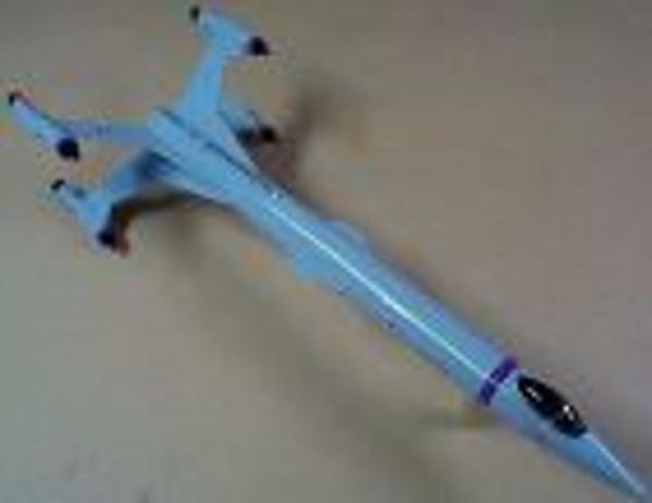
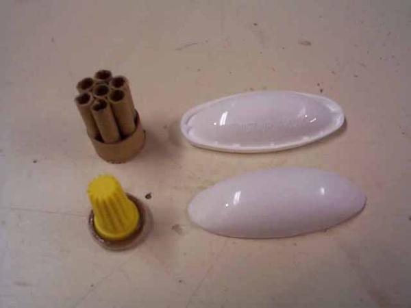
Photo-1: On the left are a "nozzle" assembly with the Copper Head tubes and an "intake" assembly with a wire nut. The ridges on the wire nut add a bit of detail to the intakes. On the right top is an unmodified deodorant cover. Below it is the one trimmed and ready to CA to the nose cone.
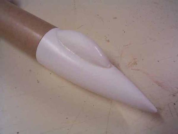
Photo-2: This is a close up of the canopy already CA'd onto the nose cone. Since I don't know the Estes part number for this particular cone, you should be able to identify it from this shot.
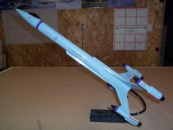
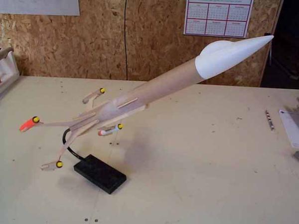
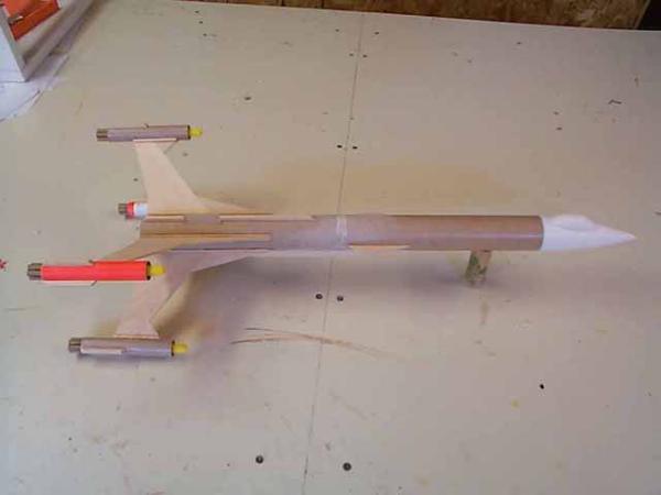
Photo-3: This is an overall view of the model, less paint of course.
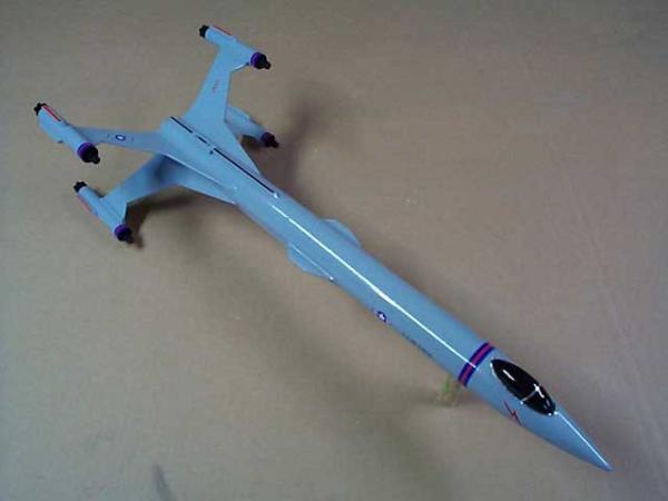
Photo-4: A side view of the model. It doesn't show up well, but the disposable razor cover can be seen between the two dorsal basswood strips.
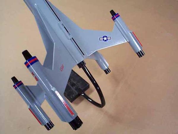
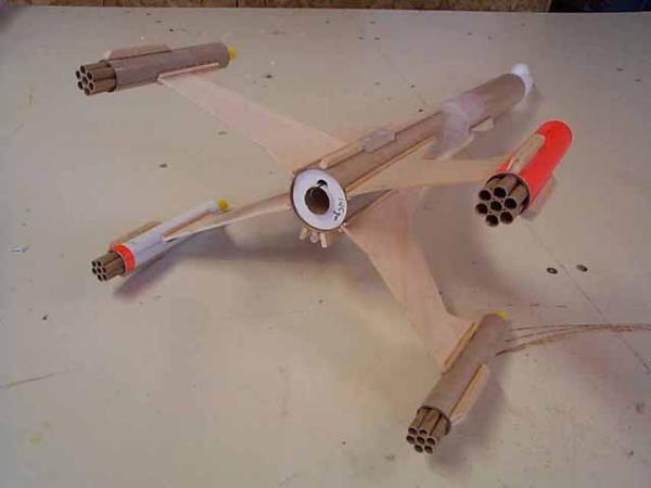
Photo-5: Rear view. The fuselage strips, root strips and the orientation of the wings show up well in this view.
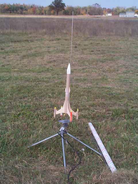
Photo-6: On the pad for maiden flight. Unfortunately, I didn't get a usable photo of it at lift off.
|

 |
 |