| Manufacturer: | Scratch |
The Oat Propulsion Laboratory presents our latest Descon 10 entry

by Emmanuel Camburako
 The
Name
The
Name
Descon 10 - Roman numeral 10 is X. Typical designation for an experimental
aircraft is X. Thus, this experimental aircraft designation is the X-10 or X-X.
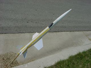
Double X
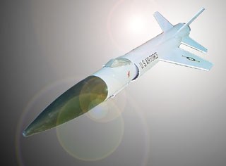
The Double X has been designed as a vehicle to investigate the practical application of a ground to near earth orbit manned intercept vehicle. The mission for such a vehicle would be to take off in a conventional manner, attain a low orbit, intercept hostile incoming weapons systems and return safely to home once again.
Mission Parameters
For this project it was determined that in order to be competitive in the
current market the NEO intercept vehicle would be designed and built using
existing technology and off-the-shelf parts (Gemini DC). To keep research and
development costs to a minimum only existing airframe, motors and tooling would
be considered.
 The
Parts
The
Parts
Use this link to view the list used for the design and construction of the
Double X near earth orbit intercept vehicle.
Parts list
The only variation from the parts list is that balsa nose cones were used
for the NC-20's. Typical plastic NC-20's may be used but the construction
technique originally used balsa. For simplicity balsa was used for this
application.
The Design
As with most designs, inspiration is is the most important part of the process
and the most elusive element of the method. The long list of past and present
X-planes and rockets had a great impact on the source of inspiration. The most
obvious influence is the famous Douglas X-3 Stiletto. Less obvious is the
Estes Rocket
Plan #55 a.k.a. Excalibur which can be viewed on
JimZ's site.
Critical construction techniques were borrowed from this very nice design.
Missing from this entry is the traditional oat cereal box which has become the
trademark design element of the OPL.
Sorry kids, maybe next time...
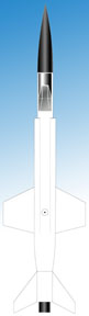 The templates needed are
included through links on this page.
The templates needed are
included through links on this page.
The general layout design and preflight testing was done using VCP and SpaceCad. Both files are included here. Because of the relatively complex nature of the airframe cross section it was necessary to simplify in the simulation.
Construction
As stated in the description part of the construction technique is taken from
the original Excaliber. This is important as there is a newer version which
does not employ the same construction methods.
 What this applies to is the engine nacelles so we'll do
that first. Split both of the BT-20 recovery system pods from the Gemini kit in
half lengthwise avoiding the ejection duct holes. Cut one NC-20 in half
lengthwise to be glued into one end of each of the tubes you just cut. The next
step is to make the nacelle assembly fit to the contour of the main airframe
BT-50 by gently sanding away the part of the n/c that interferes. Wrap a
sheet of fine grit sandpaper around a BT-50 (reinforcing the tube with couplers
or whatever is a good idea) and slowly sand inside (hollow) part of the nacelle
assembly back and forth lengthwise. Test fit often.
What this applies to is the engine nacelles so we'll do
that first. Split both of the BT-20 recovery system pods from the Gemini kit in
half lengthwise avoiding the ejection duct holes. Cut one NC-20 in half
lengthwise to be glued into one end of each of the tubes you just cut. The next
step is to make the nacelle assembly fit to the contour of the main airframe
BT-50 by gently sanding away the part of the n/c that interferes. Wrap a
sheet of fine grit sandpaper around a BT-50 (reinforcing the tube with couplers
or whatever is a good idea) and slowly sand inside (hollow) part of the nacelle
assembly back and forth lengthwise. Test fit often.
Glue a BT-20 thrust ring to a piece of card stock, carefully cut out the circle when dry and bisect the assembly. Sand the flat edge of the semi-circle to fit the main airframe. This will become the inlet of the engine nacelle and will be painted black.
Using the fin templates cut out each of the fins making note of two of each one being left and one being right side. Use typical fin techniques.
 Trim
BT-50 to 14.5 inches in length. Mark tube using alignment guide for all of the
lines. These parts line up at odd angles, so pay close attention to which part
goes on which line.
Trim
BT-50 to 14.5 inches in length. Mark tube using alignment guide for all of the
lines. These parts line up at odd angles, so pay close attention to which part
goes on which line.
The motor mount will protrude 1/2 inch from the back of the rocket. This will eventually be painted black. Use whatever motor retention device you are fond of.
Typical shock cord and parachute mounting using one of the 12 inch chutes.
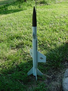
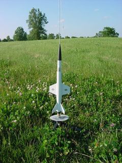
Flight
The flight simulation and actual flight reports can be viewed from this page.
Flight simulation using the prototype design layout in SpaceCAD.
|
Launch |
||||
| Flight Number | Flight #1 | Flight #2 | Flight #3 | |
| Date of Launch | ||||
| Launch Location | SMP, KS | |||
| Payload | Description | none | ||
| Weight | ||||
| Recovery System | Type | Plastic Parachute | ||
| Color | Orange/White | |||
| Engines: No. of/ Type | 1st Stage | B6-4 | ||
| 2nd Stage | - | |||
| 3rd Stage | - | |||
| Total Weight | ||||
| Method of Launch | standard | |||
| Launch Angle | 0† | |||
| Predicted Altitude | ~400 ft. | |||
| Weather |
||||
| Wind Direction | West | |||
| Wind Velocity | 10 - 15 mph with gusts | |||
| Humidity | high | |||
| Temperature | 95†F | |||
| Visibility | unlimited | |||
| Remarks | clear sky | |||
| Flight Data |
|||||
| Estimated | |||||
| Altitude | Tracking Information | ||||
| Computed Altitude | |||||
| Flight Duration | too short | ||||
| Stability | |||||
| Flight Performance | prang! | ||||
|
|
The Oat Propulsion Laboratory is located in Overland Park, Kansas. To contact our design engineering staff (me) click on the link below: The OPL was also responsible for the Oatlander design in Descon #8 and the Big Red Rocket Painted Blue, Quick-Oats X from Descon #9. The Oat Propulsion Laboratory uses only pure natural ingredients and no additives or preservatives.
|

 |
 |