| Manufacturer: | Scratch |
|
Which came first? The Egg? The Chicken? Or..... The Rocket! |
|
|
The Tale of Egberto
Guismonte - The Rubber Chicken Rocket
|
||
| PARTS LIST:
|
|
ADHESIVES: |
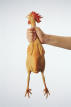
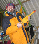
| Its all Chris Eilbeck's fault he came up with this idea to fly some rubber chickens at the m.a.r.s. Brass Balls launch. His was to be called Keith. Well it seemed like a good idea at the time. I hadn't originally planned to enter it for Descon so I dont have a lot of construction details for the early stages suffice to say " First catch your chicken..." I got mine from the Silly Jokes Online Store. |
||
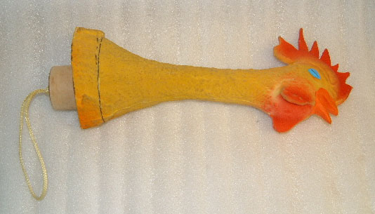
The Chicken has landed |
|
| A couple of days later and I had a box full of rubber chickeny goodness. I had decided this chicken had to go with a whoosh which meant a 38mm motor mount and a Cesaroni Pro38 motor as Aerotech motors are as rare as hen's teeth over here in the UK. |
Chicken Stuffing |
|
|
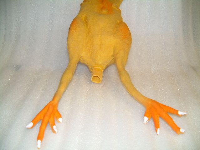
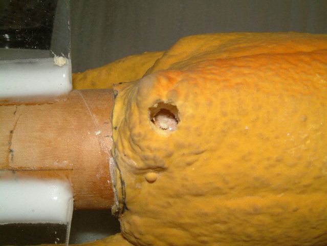
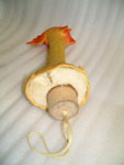
Having aquired my new bird the next question had to be how to fit the motor. It wasnt difficult to imagine where it had to go just how to go about putting it there. I started by removing the squeaker fitted to the chickens aft vent. |
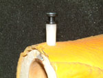
| The next step was to take a piece of 38mm motor mount tube and offer it up to the chicken's bottom. I drew a line around the tube and then cut out the rubber with a pair of sharp scissors. I emphasise the sharp as chicken rubber it quite resiliant and difficult to cut. A bit of trimming with a scalpel and I had an even tight fit. I fitted the motor mount in to the chicken and pushed it up until it was in the neck of the chicken as far as it would go. I then offered up a Pro38 1 Grain casing to get an idea how far the motor mount would have to hang out the back of the chicken. I figured that the tube within the body of the chicken would be adequate for the recovery system as long as the majority of the motor was outside the body. I added around 10mm to give a bit of space for motor retention below the fins and cut the motor mount tube to length. | |
|
In the past I have used a piece of 1/4" fibre glass rod as a mounting point for the recovery harness. I drilled a hole across the tube above where the end of the motor would go, cut the fibreglass rod to length glued and filleted it inside the tube and the filed and sanded the end of the rod smooth on the outside of the tube. |
|
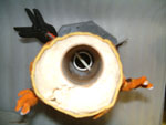
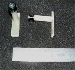
With the motor mount trimmed it was time to make the "nose cone" fitting. Now things get a bit vauge here and I will have to leave the detail as an exercise for the student. The idea was to make something from a 38mm coupler tube with some space in it which could accept some beak weight. I rummaged and came up with a selection of Estes bits and bobs. A bit of sanded centering ring here and a bit of glue there and I had a part that would fit in to the neck of the motor mount tube. The only evidence I have of this is in this picture sequence. |
|
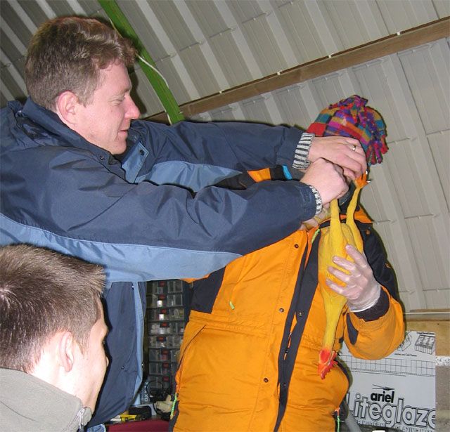
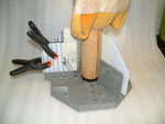
With the nose piece made it was time to get foamin'. My plan, which proved rather unsuccessful, was to fit the nose piece to the top of the motor tube using masking tape to hold it in place. Pour in a quantity of two part foam to the rubber chicken carcass. Jam the tube assembly up the chicken and wait for the foam to expand and set. Fixing the whole thing in place. As the join between the nose piece and the motor tube were flush at the top of the tube and the tube should fit snuggly in to the chickens rubbery neck I reasoned that, once set, I would be able to cut through the rubber and seperate the now foamed on head and nose piece from the foamed in motor tube and chicken body. The masking tape should have held the nose piece in place and sealed it from foamy ingress. |
|
|
|
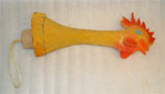
There lies my error. That two part foam can build up a fair pressure if you contain it. With the foam mixed and poured in I jamed in the tube assembly. I wiggled and tipped things around to get a even distribution of liquid foam around the insides then settled down to hold it all in place. The foam expanded and started to push. It was quite a fight,and quite a sight as I struggled with my fowl. In time I triumphed, or so I thought, and the foam set with the tube where I thought it should be and a reasonably firm chicken (even if it's head had swollen in a rather disturbing fashion). |
|
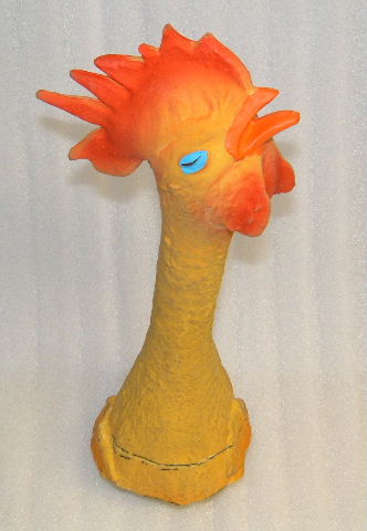
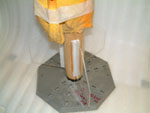
Time to make a quick cut and "off with its head". First cut through where I thought I had to cut and the head refused to budge. A spell head scratching, cursing, asking others for guidance and being told "you didnt want to do it like that" later and an second calculated cut was made. This time the head came off in my hand. Some modification and fettling and I had a useable head / beak / nose cone. The reason for the cut point moving was that the pressure of the expanding foam had forced the inner nose piece back down the inside of the motor mount. The second cut was measured from the position of the aft end of the nose piece relative to the back end of the motor tube. With the length of the coupler used for the nose piece know it was possible to work out where the front of it should be. Measure along the outside of the chicken and cut through. |
Fin Fitting |
|
 |
Now
it was time to add the fins. I didnt want to spoil the lines of my chicken so I
opted for clear plastic fins. I had wanted to use polycarbonate as it is much
more resiliant but couldnt source any in time so I had to settle for Acrylic
sheet. I measured three pieces of 2mm thick acrylic 100mm (root) by 85mm and
then cut off a corner at 45 degrees 50mm in from the edge. The trusty Estes fin
alignment jig was used to attach the fins. An old Pro38 single grain casing
with the nozzle drilled out to take the 13mm motor mandrel for the jig allowed
me to use the Pro38 casing to centre the chicken on the alignment jig. |
 |
|
 |
Launch Lugs |
 |
 |
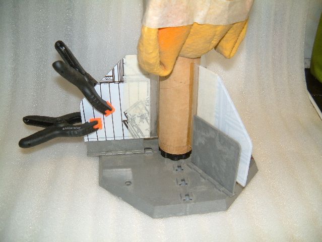
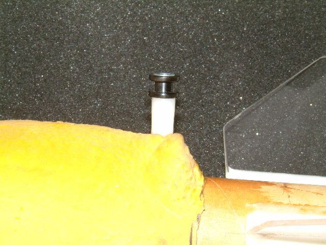
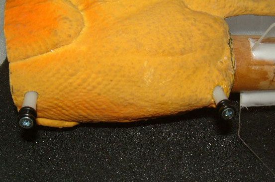
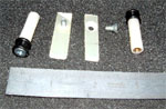
Time for some launch lugs. With the main body tube / motor mount such a thin wall and not wanting to have anything through the wall for either the aft or forward launch lugs I had to come up with a solution. The launch lugs also had to be on stand offs to be able to clear the portly carcas of the checken. The best side to mount the lugs was on the back. The chubby chickens foam filled belly being a stand off too far. The easiest way I could come up with was to take some 25mm long 0.325" diameter nylon PCB stand offs with an M4 brass threaded insert in either end. Some small strips of 3mm thick fibreglass around 6 mm wide and 20mm long were made. A countersunk 4mm clearance hole drilled at one end on each. The standoffs were attached with a countersunk screw. At the other end two 1/4" delrin rail buttons were countersunk on one side and attached with another countersunk screw. The chicken was carefully measured, marked up, cut and drilled. Slots were carved in the foam from the aft end and the front end along the tube wall to allow the fibreglass strips to be pushed in. When all the preparation was complete the slots and strips were epoxied up, the strips, with screw in place, pushed home along the body tube and the assembled pcb standoff and rail button screwed down on to the thread of the fastner sticking up through the pcb strip. | |
 |
||
 |
||
 |
|
|
Recovery Harness |
|
|
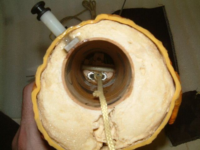
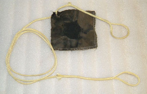
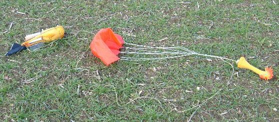
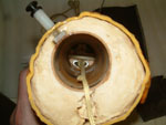
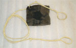
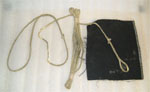
I had a bit of a rethink on the recovery harness mount at this point and decided to beef it up with a 38mm plywood bulkhead. I attached a wire rope clamp as a tiny u-bolt and cutaway a fair portion of it to allow the ejection charge through. As a last minute add on it only just fit above the top of motor when it was fitted. The assembly was glued in with 12 minute epoxy. The chicken body end of the recovery harness was made from approx 1.5m of narrow tubular kevlar with loops made at either end by the excellent "pull it through itself" technique. A bit of carefull fiddling with a bit of bent wire allowed it to be threaded through the mini u-bolt and then back on itself in a catspaw knot. A small 3"square of nomex was cut for a flame shield and a larger 5" square cut to wrap around the 18" 'chute. |
 |
|

|
|
Beaky |
|

|
Finally I had to add some beak weight and the beak retention end of the recovery harness.. A loaded single grain Pro38 was fitted to the rear and then lead shot was added to the hollowed out nose piece until the CofG was agreeably forward. The lead shot was mixed with 5 minute epoxy to make a nice batch of rocket caviar and was poured in and left to set. A 38mm plywood coupler bulkhead had a single approx 5mm hole drilled through it. A length of tubular kevlar was folded in half a had a figure of 8 knot tied with the two free ends held together to form a loop. This was threaded through a 5mm washer. The knot was large enough that it wouldnt pull through the washer. The loop was then pulled through the bulkhead and the bulkhead glued in to the back of the nose piece with epoxy. |
|
|
Pre-Flight Chicks |
|
 |
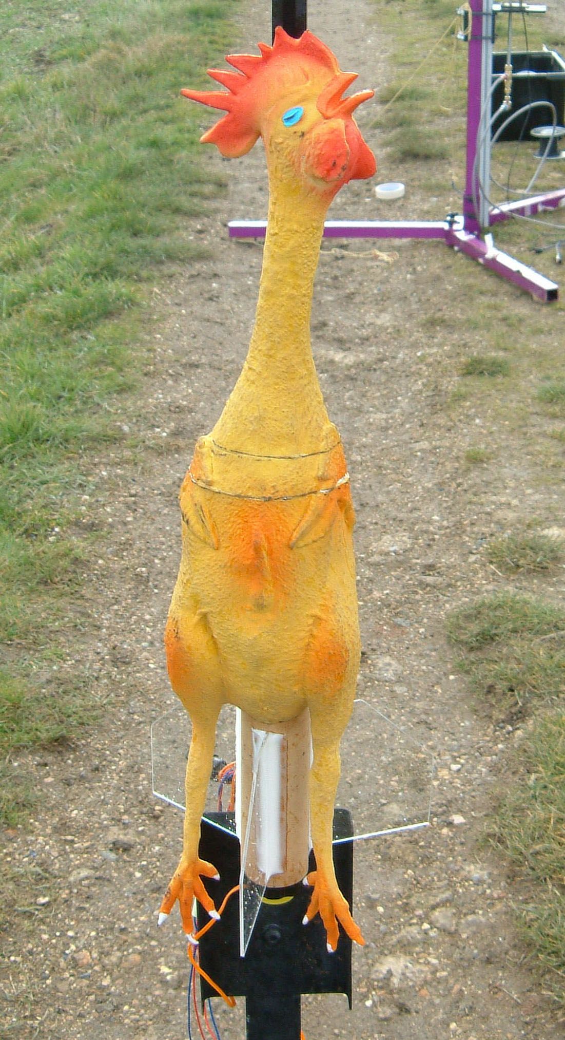
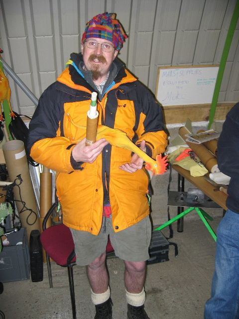
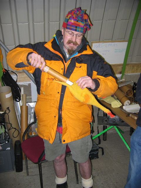
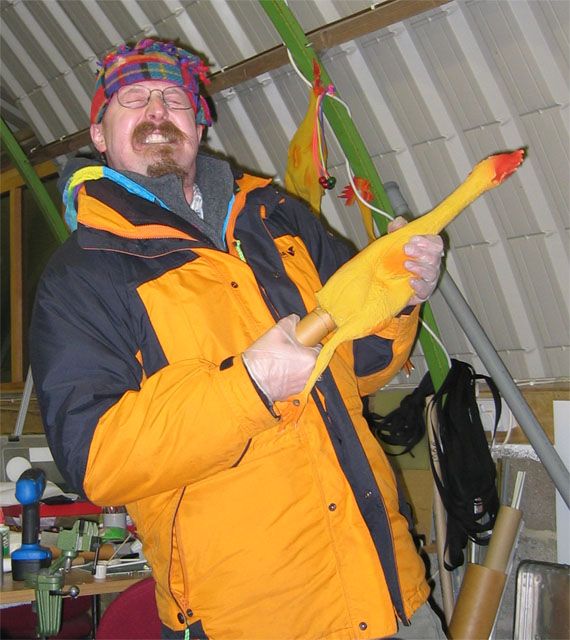
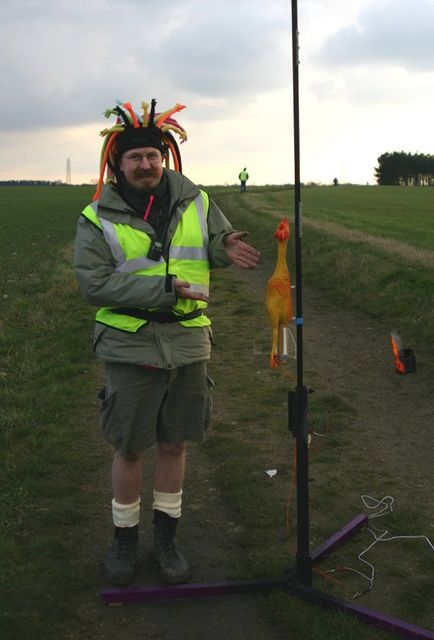
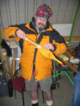
Well there we were launch day. Chicken rocket had a fully fitted recovery system and was loaded up with a Pro38 Smokey Sam 1 grain reload. The rocket weighed in, fully assembled without the motor at around 750g. As the Chicken hadnt got the faintest sniff of any modelling software and was all done by eye and gut feeling I thought the best thing would be to do a spot of chicken swinging. A suitable length of string was located an the swinging commenced. Little did I know that I was being filmed so I present here for your enjoyment the fabulous, the marvellous, the stupid... chicken swing test |
| Right Click and and
"Save as" to get the swing test video (2.8Mb) |
|
5, 4, 3, 2, 1..... Make chicken go NOW! |
|||
 |
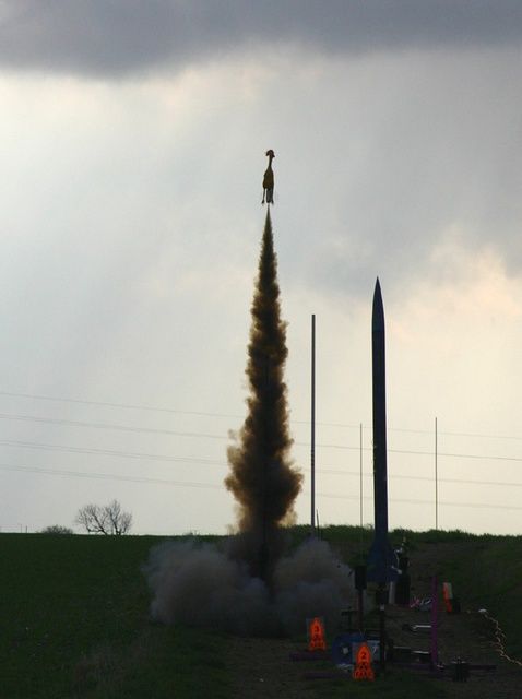
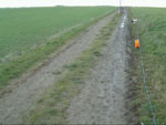
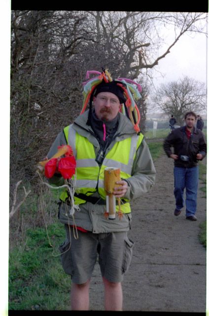
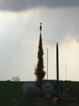
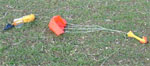
The swing test completed the rocket was carted off to the pad and loaded on to the rail. After a wait for my turn at the controller the RSO called me forward. 5, 4, 3, 2, 1, LAUNCH!.... The Pro38 lit instantly as the do so well and the chicken shot off on a thick plume of black smoke. It arced over a tad in the breeze but ejected fine and drifted gently back to the ground. | ||
 |
 |
Right Click and and
"Save as" to get the first flight video (2.8Mb)
|
Right Click and and
"Save as" to get the second flight video (2.9Mb)

|
Recovery, De-brief and Thanks |
|
 |
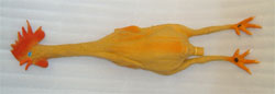
The
chicken was in fine condition on recovery. No damage to the fins or recovery
system. I was very pleased with the way the whole project had gone. I did break
a fin on a subsequent flight and am now looking to source some polycarbonate to
replace the fins with. If you have any questions about Egberto Guismonte the Chicken Rocket then please feel free to mail me at "chicken-rocket @ mikerobe.org" This page is copyright Mike Roberts 2004 except for images and video from Bob Arnott, Nial Oswald, Ben Jarvis, Pete Davy and Steve Randall who retain their copyright. |
|
|


 |
 |