| Manufacturer: | Scratch |
ETV2/Crumple Zone
By Naill Oswald
Brief
A 2-stage, clustered rocket designed to fly on 24mm Estes motors, with an interstage timer and parachute recovery of both stages, intended as a testbed for home-made electronics.
Background
Back in September 2003, I decided that I would build an altimeter for my A2 Systems and Control practical project. I started off by taking early prototypes up and down the hills of Bedfordshire (all 300 feet of them!) in the passenger footwell of my car, but obviously I would need to conduct flight testing. From the outset I intended to build two circuit boards, and a rocket to fly each in. The prototype/research unit would fly in a BT-60 based rocket with a single 24mm mount and an optional booster stage, and the final design would fly in a larger, BT-80 based rocket. I named the rockets ETV1 and ETV2, with ETV standing for ‘Electronics Test Vehicle’.
The prototype PCB was designed as a datalogger, with sufficient memory to store about 6 minutes of data at 85 Hz sampling rate. My intention was that ETV1 could be taken to a launch, and flown 5 or 6 times in one day to gather as many pressure curves as possible to see what sort of data I could obtain. However, it didn't quite work out like that, and ETV1 and its payload flew only once in November 2003. I then had a pause in launching until February (a pause which hurt!), when ETV1 flew twice, collecting two good traces, despite being 0 for 3 on successful recovery! With the PCB reprogrammed to act as a peak reporting altimeter, ETV1 flew again in March, but the payload did not give a reading, though the recovery was flawless. In May, at Big EARS, the payload flew and reported an altitude of 165 metres, which agreed with the sims for the rocket.
In the end, as with so many school projects before, the altimeter only really came together in the last few weeks, so was never flight tested as a complete unit, and will not be until Mr Examiner has finished with it (it did get me 117 of 120 available marks though!). The closest it got to flight was a makeshift pressure chamber, but everything looked good for a flight test.
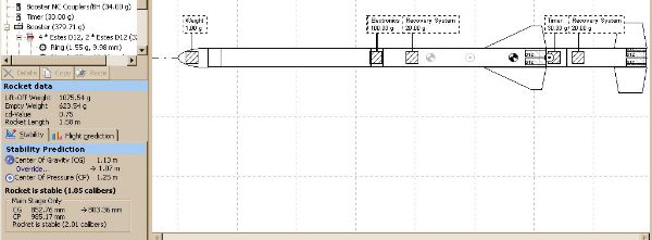
As for the rocket….I had purchased all the parts for the rocket months ago, and had assembled the components in bags ready for assembly. The design was set up in SpaceCAD, and was basically an upscale of ETV1, which by this time had flown 5 times, but never in 2-stage config. At some point before UKRA2004, I went back to the design in SpaceCAD, and still harboring some hope of having an altimeter to fly in it, gave up on the idea of a precise upscale and decided to make a big, cool looking rocket. I didn't change the design much, but I extended the body tubes to give the rocket an overall length of around 5 feet.
There were various stages of faffing with the design, and several false alarms when SpaceCAD threw up some very odd numbers (I'm using an old and buggy demo version of SpaceCAD3), but in the end I came up with something looking quite military, and most definitely the biggest, most powerful rocket I'd ever built. To get it off the pad safely with the likely mass, I added an additional pair of 24mm mounts to the booster stage's original 4, with a further 4 in the sustainer. I'm not sure how I planned to arrange staging at this point, but much of the finer details would be sorted out during construction.
The Timer
I realized that if I wanted to put a ‘chute on both stages, which was likely to be a good idea given the weight of 6 empty Estes D's, I would need to arrange electronic ignition of the upper stage. I could have gone down the commercial route, and picked up an XAVIEN or Perfectflite timer for 20 quid or so, but being so disposed, I decided to design and make one myself. I'll describe the timer design next, since I think this puts my report in some kind of logical order. As I remember it, I designed the rocket, designed the timer, and then gradually got the whole lot together.
Having become familiar with the PICAXE range of pre-programmed PIC micros, which run a BASIC interpreter, and are very easy to program, I decided not to mess around with 555s and use a PICAXE-08 as the brains of my timer. For a little over a pound, you get an 8-pin chip with 128 bytes of program memory (about 40 lines of BASIC IIRC), 5 I/O pins (1 fixed input, 1 fixed output, 3 2-way) with serial communication and a basic ADC on pin. (Check www.picaxe.co.uk for details). Perfect for a simple single event timer, with a degree of programmability.
The circuit is very simple, there are three outputs and one input. The input is a g-switch, which uses a sprung contact, and closes at 2.1 G (nominally). The outputs are an LED, a small buzzer, and the firing line. The firing circuit uses a VNP7N04 logic-level MOSFET to switch current to the igniter terminals. There are two sets of terminals, arranged in series to allow a safety switch to be wired into the system to isolate the igniter before launch. The firing power is provided by a GP23A 12v ‘lighter' battery, which charges a 4700uF capacitor. My tests showed that this was ample to fire an e-match, and makes a nice fat spark when shorted too!
The PICAXE is powered by a separate battery and regulator circuit, and has the standard PICAXE download circuit on-board to allow in-situ programming. I wrote a simple program, which looked for the G-switch closing for 200 ms, then waited a specified time before firing the output channel and then continuing to beep to aid location of the rocket.
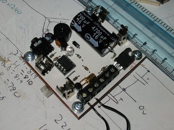
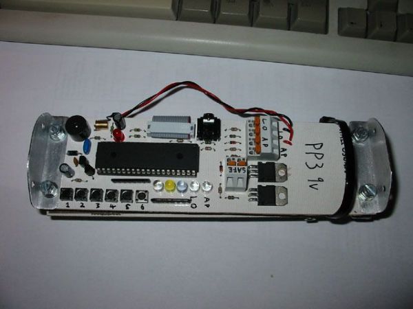
In the usual fashion I designed my artwork, printed onto tracing paper and exposed, developed, etched and drilled the PCB at school. I populated and tested the PCB at home, which gave me an excuse to make a bang in the back garden with a length of quickmatch (more on QM later…).
The Rocket Design
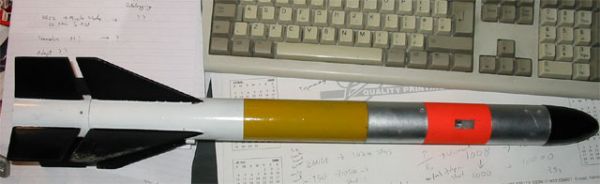
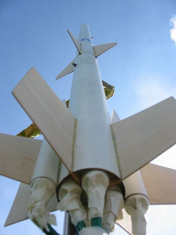
The basic design of the rocket was decided fairly early, and the final design is more or less the same as intended, except in dimensions Its not really anything new or radical, but was intended to be somewhat like a sounding rocket (in keeping with its intended use as an electronics test rocket). From the top the rocket is configured as follows:
- Parabolic (Fat Boy) nose cone (BT-80)
- Upper Payload/Chute bay
- Electronics Bay
- Lower Chute Bay
- 4x24m Cluster motor mount
- 4 large TTW fins
- Interstage
- Booster chute bay
- 4x24mm cluster motor mount
- 2x24mm outboard motor tubes
- 4 ‘Nike' type large TTW fins
- 2 smaller ‘Nike' type fins
Parts List
I purchased the bulk of my parts from Apollo 11 Model Rocketry (www.apo11o.co.uk), and would recommend them to anyone looking for model rocket components in the UK. Alan (though it was run by Tony Williams when I first ordered) stocks Totally Tubular body tubes, which are very high quality, and come in 34” lengths. The AET-50mf metal foil lined motor tube comes in 17” lengths, so I ordered three. I've used Apollo 11 part numbers here, but most of these parts are available from Estes (such as the BT-80 tubing).
To build this rocket you will need the following items, or equivalents:
- Estes PNC-80FB ‘Fat Boy' Plastic Nose Cone (1)
- Estes PNC-50Y BT-50 x 106mm Ogive Nose Cone (2)
- 550mm ABT-80 Body Tube (2)
- 395mm ABT-80 Body Tube (1)
- 70mm ABT-80 Body Tube (1)
- 50mm ABT-80 Body Tube (1)
- 100mm ATC-8004 Coupler Tubes (3)
- 80mm AET-50mf Motor Mount Tubes (8)
- 115mm AET-50mf Motor Mount Tubes (2)
- AEB-50HD Motor Blocks (24mm Heavy Duty) (10)
- 4x24mm into BT-80 Centering Rings (3mm ply) (4)
- BT-80 Coupler Bulkheads (3mm ply) (4)
- 190mm x M6 Studding (2)
- M6 full nuts (10)
- M6 washers (10)
- Screw Eyes (approx 10mm eye dia) (4)
- Motor retainer plate for booster (1)
- M4 screw (1)
- M4 washer (1)
- M4 PCB spacer (1)
- AEH-02 Motor Hook (70mm) (4)
- ALL-0406 6mm Launch Lug tubing (100 mm)
- 2mm LitePly sheet
- AKC-0100 1mm Kevlar shock cord, 100 kg test (2 metres)
- AFE-0605 5mm Elastic shock cord (3 metres)
- 24” ‘Chute for booster
- 36” ‘Chute for sustainer
- 2 Personal Alarm Audible Bleepers (£2.50 from Rockets and Things)
- 9” Square Nomex ‘Chute protectors (2)
- Small (220 lb) Quick Links (2)
- Standard Plastic Rail Buttons (2)
- Staging Timer
- GP23A Batteries
- Tufnol/G10 for electronics bays
- 30-minute Epoxy (I used Pacer ‘Z-Poxy')
- Sanding Sealer
- Sandpaper
- Spray Paint
- Construction Tools (Scalpel, mixing sticks etc)
There's a lot of parts, but I think that's pretty much it. Many parts of this rocket could be built using the builder's personal preferences, and there are certainly things I would do differently.
The centering rings were custom made for me by Tony Betts of Physics of Flight, as were the bulkheads. These might be the only parts needed that are hard to come by, but for UK fliers, Apollo 11 now stock cluster centering rings, and these look to be of a similar quality to the ones I bought. I think Rockets and Things are also doing cluster rings now, so upgrading BT-80 kits to F impulse should be a bit easier. The only problem with the CRs was that with the thick-walled motor tubes, there was very little material left, so they were quite delicate. However they would be epoxied, so this would not be too much of a problem.
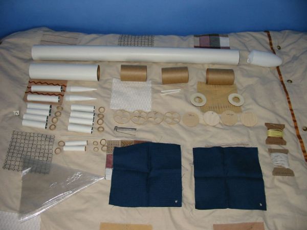
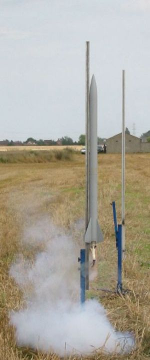
Construction
It's been a while since I built this rocket, so I'll try to keep things roughly chronological and ordered. I started by cutting all the tubes to length, and assembling all the parts. [Photo]. I then epoxied the 10 motor blocks into the 10 motor tubes, and numbered all the tubes. The 4 which would go into the upper stage were marked and cut for motor hooks when set and test fitted. I also had to use a small file to notch the centering rings for the sustainer to fit the motor hooks. With this done, I assembled the motor mounts, using 30 minute epoxy throughout. The sustainer MMT assembly also has a length of 6mm launch lug epoxied into the centre, to act as a wiring conduit for airstarted motors, if desired. The booster MMT had a screw eye put into the top CR and (before being put together) a 4mm PCB spacer put into the lower CR. The PCB spacer allows a motor retaining plate to be screwed down to hold the central 4 booster motors in place.
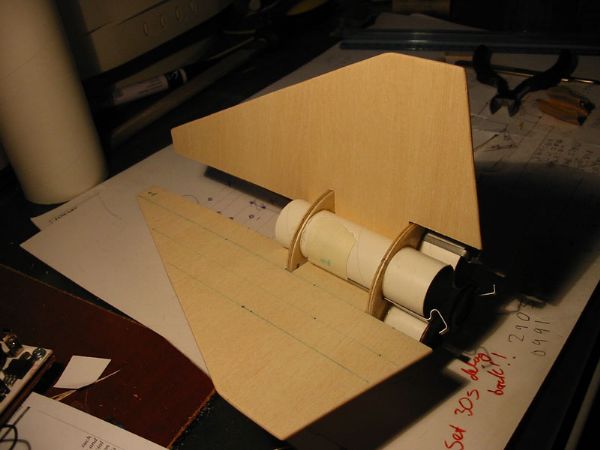
With the motor mounts assembled, I set about making the fins. I had hoped to use my school's new CNC machine to cut the fins out, but after several hours of trying we could not get this to work. I resorted to the trusty Swann-Morton scalpel, metal ruler and cutting mat. My fin material was 2mm LitePly, acquired from a local model shop. It is a plywood with a balsa core, so it is stiffer, stronger and more durable than balsa, but is still very light compared to plywood. I found it easy to work with, and the only disadvantage was that it seemed to be prone to warping, though this may be because I bought my sheet several months before putting it to use. I found that LitePly made very strong, yet light fins, with much better durability than balsa.
I cut out the fins according to the dimensions I had arrived up on in SpaceCAD, leaving a large tab for TTW mounting. The TTW tab was longer than needed, so I could carefully trim it to the correct depth. The fins are designed to fit between two motor tubes, contacting each where they are closest. I marked and cut the fin tabs to fit to the CRs with the motor mounts out of the body tube, and was able to conduct a full dry fit before assembly. Each fin and motor tube was numbered, so the fins were cut and adjusted to fit well in the correct place, which makes up for any mis-alignment of the CRs. With the fins sanded smooth and rounded, and the tabs cut, I attached the Kevlar leaders to each motor mount. Lacking a screw eye, the sustainer MMT assembly simply had the Kevlar tied around a motor tube and run out of the open top of the upper CR (the center section was long lost, having broken a while before).
The motor mount assemblies were then epoxied into the body tubes, and allowed to cure. At this point, I marked out on each body tube (booster and sustainer) where the fins would go, and where the centering rings were located. I then carefully set a line of masking tape on the body tubes for each fin slot, and made a single scalpel cut the length of the fin slot. Continuing with the careful scalpel work, I enlarged each fin slot until the fin fit well. All my fins and slots were numbered, so each fin could be fit exactly to its particular slots. I ended up with a few gaps on some of the fin roots, but nothing an epoxy fillet wouldn't cover.
The next step in my unconventional TTW procedure was to epoxy the fins in place. I made sure everything would fit first, and was happy with the alignment of the fins and the fit to the motor mounts. My attachment technique ended up being rather on the heavy side, since it involved carefully feeding epoxy through each fin slot to make the root bond. The cluster motor mount mean that I was bonding each fin between two motor tubes, so there was quite a gap to fill. I think the centre of each motor mount is pretty much solid epoxy, but the fins are very solidly bonded to the motor mounts. All the fins were then filleted externally, using my preferred ‘gloved finger' method, followed by sanding to a smooth radius.
I did this on both stages, and ended up with fins that feel a lot stronger than balsa fins of equivalent size, and which are also much tougher, being less flexible and less easily damaged.
 I turned my attention to the
booster stage, which required outboard motor tubes to be attached. These have
separate nose cones, which are bonded into the forward end of each tube, and
are then surface bonded to the booster airframe. Again 30-minute epoxy was
used, and the outboards were held in place with tape while the epoxy cured.
Following this, the outboard fins (smaller copies of the main booster fins)
were CA'd and then epoxy filleted to the outboard tubes. This pretty much
completed booster construction, if the interstage is considered separate.
I turned my attention to the
booster stage, which required outboard motor tubes to be attached. These have
separate nose cones, which are bonded into the forward end of each tube, and
are then surface bonded to the booster airframe. Again 30-minute epoxy was
used, and the outboards were held in place with tape while the epoxy cured.
Following this, the outboard fins (smaller copies of the main booster fins)
were CA'd and then epoxy filleted to the outboard tubes. This pretty much
completed booster construction, if the interstage is considered separate.
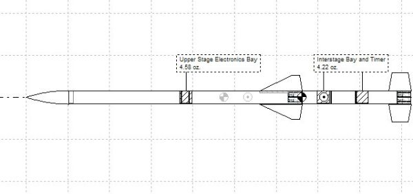
The sustainer ‘booster' and chute bay section was also more or less finished at this point. Both the sustainer and booster were drilled for rail buttons, with holes being put into the upper CR in both cases. I then built the sustainer electronics bay, which sits between the two chute bays. It is fairly standard in design, but is rather on the heavy side for an Estes-powered rocket. It consists of two coupler tubes (one cut slightly short of the original 100mm) joined with 40mm of body tube, a bulkhead epoxied into the lower end of the bay. Two lengths of M6 (1/4”) studding (allthread) then run the length of the bay. In future I would use M3 (1/8”) studding, but in this rocket the M6 studding, which is very heavy at around 100g total, acts to move the CG forward and make the rocket stable. The M6 studding is fixed at each end with nuts and washers, and between the two rods is epoxied a piece of ‘tufnol' phenolic board to act as an electronics mount.
At the time of writing, the upper electronics bay has not yet carried a payload (though the interstage has been flown in its place to test the timer), but could be used for dual deployment (in an Estes powered rocket!) or for airstarting motors in the sustainer. This would require the igniter wire to be run through the conduit in the centre of the motor mount provided for this purpose. I decided that having the igniter wire running from the e-bay to the igniter connected using an inline phono plug and socket would allow the wire to be made short, so that it disconnected at ejection. This would act to prevent tangles with the chute and to prevent the airstarts firing after chute deployment (I'm thinking of having 2 of the 4 sustainer motors lit from below, and the other two from above after ignition of the first pair).
In theory then the rocket is quite versatile in terms of flight configurations, and in original form could be set up in a variety of ways. For example the booster stage could be attached to the upper chute bay and flown as a 6-D cluster, or the interstage could be switched with the upper electronics bay, or the sustainer could simply be flown with a weighted nosecone. Originally the sustainer had two rail buttons, as did the booster (one on the booster, one in the interstage), so that the parts could be swapped around. For flight I would tend to either remove two of the buttons, or simply rotate the electronics bay to leave only two buttons in the rail.
Continuing with the construction, the nosecone and upper chute bay were no problem, since they simply fit couple to the top of the electronics bay. The interstage, which contains the staging timer, was constructed next. My mounting method, which I would not recommend, was to have single piece of M6 studding through the centre of the bay, with the timer mounted on a tufnol plate with a launch lug epoxied to the back, allowing the whole unit to be removed from the rocket. I forget the precise dimensions of the interstage, and I (as the flight report will detail) no longer have the interstage to take measurements. However the construction is fairly simple, being made again of BT-80 couplers and BT-80. A length (70 mm or so) of BT-80 holds together 2 couplers, one which forms the timer bay and coupler for the booster stage (since the interstage acts as nosecone for the booster) and the other which couples to the sustainer and provides space for the sustainer ignition bundle. I think I ended up with about 100mm of space between the sustainer MMT and the top bulkhead of the interstage timer bay. This is to allow the quickmatch assembly to fit.
The upper bulkplate was epoxied in place, and drilled for an igniter wire. The lower bulkplate was removable via a nut, and also held a screw eye for shock cord attachment. The coupling method to the sustainer also needs revision, but as I built the rocket it works by having the rear CR for the sustainer set back into the body tube by about 30mm, allowing the 30mm of exposed coupler tube to slide in around the motor mounts. Skipping ahead, the motor mounts were also recessed, so that the end of the motor hooks, not the ends of the motor tubes, are flush with the end of the body tube. This resulted in the body tube the coupler fits into being scorched, so that now the coupler only couples with a short section of BT ahead of the rear CR and the epoxy fillets on the fins, which remained undamaged. More on this later.
Last of all came the recovery system. The Kevlar leaders each had an M6 nut tied to the end, followed by a length of elastic shock cord. A nomex chute protector was fed onto each shock cord, and each assembly terminated with a quick link to allow switching around of sections. In the end I added a length of elastic between the quick link and the attachment point, and attached the parachute for each section to the quick link. The booster uses a 24” nylon chute for recovery, and the sustainer a 36” ‘Paul Lavin Special' flare chute (a mere £10), which came with a small deployment bag, which I later ditched.
Finishing
So far the rocket has not flown in its final paint scheme, the closest it has come is flying in grey primer. I won't make excuses for this, I just didn't get round to painting before flying. The first three flights were ‘naked', with no paint whatsoever. I used balsa sanding sealer to seal the fins on the booster, having found that LitePly has a tight but deep grain pattern which is hard to fill with primer, but I found this out on the sustainer, so its fins were not sealed. I found that several coats of sanding sealer, with sanding in between, gave a smooth finish on the fins. I used a combination of Halfords filler primer and Plasti-Kote standard grey primer to build up fairly heavy coats before sanding. This ate paint and sandpaper, but was effective on the tube spiral, which is actually quite small on these tubes. In future I would think about either using thickened epoxy as a filler, or using lightweight ‘glass cloth as a way of getting a smooth finish. I would also think about glassing the fins to the airframe, both for strength and for ease of finishing. With glassing, I think that the TTW mount could perhaps be done away with, since the way I did it was a lot of work, and added a lot of epoxy weight to the rear of the rocket. Using light glass (my local model shop now does 23 gram glass cloth) might well turn out lighter than the heavy TTW mount I built.
The final paint scheme is unfortunately not in place before the end of the contest, I hoped to paint up the rocket in suitably prototypical IRIS-like colours. Never mind, I quite like the look of the rocket in gray primer J
Flight Reports

I got the rocket pretty much ready to go in the week before UKRA 2004, which was my first trip to Pete's Farm, and the second big event I'd been to, after Big EARS. It was unpainted, but ready to fly in a variety of configurations, including full-up two stage. However I planned to build up gradually, and fly on single stage clusters, especially since my clustering experience was a little limited at this point.
I turned up at UKRA on the Saturday some time before lunch, and managed to find some space on Darren Longhorn's (of TB3 fame amongst other things) table, in which I could prep the rocket. I started off by setting up the recovery system, and then moving the interstage into the position of the main electronics bay. The booster, sustainer, electronics bay and interstage all had rail buttons fitted, so they could be moved around like this. The timer was set up to simply fire an e-match, flapping loosely in the upper chute bay, which would fire about 2 seconds into flight. The intention was to establish that the timer would actually fire at some point during flight, which was the best test I could do.
With the recovery system and electronics prepped, I could start the interesting part…the motors. For the first flight I assembled 4 D12-5's, a metre of quickmatch and a few inches of PIC slowburn fuse. I cut the PIC into 1.5 cm lengths, and stripped the outer plastic sleeve, to expose the fuse material. A length of this was then placed into each motor nozzle, after the nozzle was cleaned out with a brush and checked for signs of clay on the propellant. The quickmatch was cut into 4 sections, and the outer sleeve of each section was cut down by around 2 inches. A length was used for each motor, and one of the two strands inside the quickmatch sleeve was inserted into the nozzle with the PIC fuse. The other strand was then pushed into the top of the nozzle to hold the rest in place. This meant that in each motor, quickmatch and PIC was in contact with the propellant, to try and make sure all the motors lit.
With quickmatch in all four motors, they were taped with masking tape to hold the QM in place, and then inserted into the motor mount. The exposed ends of the QM were brought together, an Estes igniter inserted into the bundle (8 strands) and the whole lot liberally taped up with masking tape.
I can't remember how the timing went, but at UKRA I was fairly relaxed about launching (only 4 flights in the weekend), so I think the rocket was prepped a long while before I actually launched (I launched at 5:15 in the afternoon, very slack!). When the time came, I took the rocket out to the (shiny new UKRA) pad, and slid the rocket onto the rail. I hooked up the igniter leads and returned to the launch controller, to await the countdown. When I pressed the button, the ignition bundle burned rapidly with a whoosh, and lit all four motors, generating quite cloud of smoke. The rocket boosted straight and true into the overcast sky, with quite a sound from the 4 D12 motors. This was the first ‘proper' cluster I'd built and launched, and I was very pleased with the results.
The four ejection charges deployed the parachute with no problem, and the rocket floated down very slowly to land in the field behind the launch pads, not far away from the pad at all. On recovering the rocket, I found that all was not well. Firstly, the brand new parachute had acquired an unintended spill hole, but despite this was very effective on the way down. More worryingly, the rear of the rocket was well and truly toasted between each pair of fins, where the interstage coupler should connect the two stages. I had underestimated the toasting power of 4 D12s, and the motors being set around 10mm into the body tube cannot have helped. I mentally scrubbed plans of a two-stage launch at UKRA, since the damage looked bad enough to require some decent attention.
Flight No.2 took place at the end of the Sunday of UKRA04, when a few of us went down to the range and flew in the evening. I had ETV2 prepped as before, but with 2 D11-P's, and 2 D12-5's to try and prevent scorching the chute more. The ignition bundle was prepped as before, but this time only three motors lit. I didn't know this until I recovered the rocket, it didn't seem to make any difference to the way the rocket flew. The motor that failed to light was a D11-P, with the white crumbly type of nozzle clay. Estes motors seem to either come with this stuff, or a much better, harder clay which doesn't seem to cause as many problems. On later inspection the motor was found to be well and truly blocked with clay.
Worse than the non-ignition was that the parachute never deployed – I had re-rigged the recovery system, but connected the parachute and deployment bag in such a way that the shock cord between the parachute attachment and the deployment bag attachment point was shorter than the parachute shroud lines. The rocket tumbled back to the ground, and landed heavily. However on recovery I found that the rocket had suffered no damage, other than a little muddy scuffing on two of the fins. This convinced me that LitePly is definitely a good fin material, and I don't think that 2mm balsa would have survived such an impact.
I gave my camera to Damian Hall to photograph the flight, and he shot a very nice sequence from liftoff to landing.


Flight No. 3
The big one – two stages, both clustered. 10 motors, lots of quickmatch, 156 Ns of BP motors!
The launch was EARS June monthly launch, which turned out to be a good day for flying rockets. I started by preparing the motors, cutting 10 lengths of quickmatch and slowburn fuse, and assembling the 10 motors. The booster contained 2 plugged C11-0's, 2 plugged D12-0s, a D12-3 and a D12-5, and the sustainer contained 2 plugged D12-0s, 1 D12-5 and 1 D12-7. In the usual fashion the quickmatch and slowburn was installed into the motors, and all taped up with plenty of masking tape. I can't remember how long this took, but I was sat at my table prepping for a while, but I was in no particular hurry. Next I prepared the recovery systems in each stage, and readied the interstage timer for flight. This involved running wires from the output terminals to a terminal block (to make connecting the sustainer e-match easier) and installing fresh batteries. With this all done, I had lunch, and then though about heading out to the pad.
I will also add that between UKRA and this flight, I had extended the booster airframe to 395 mm (from the original 295) to allow more space for the recovery system, and I had swapped the ‘Fat Boy' nosecone for an ‘Executioner' ogive nosecone. I think this adds to the sounding rocket look. The timer was set up with a keyswitch for power and a jack-based pull-pin as an igniter safety feature. When the pull-pin is in, the igniter is disconnected from the timer.
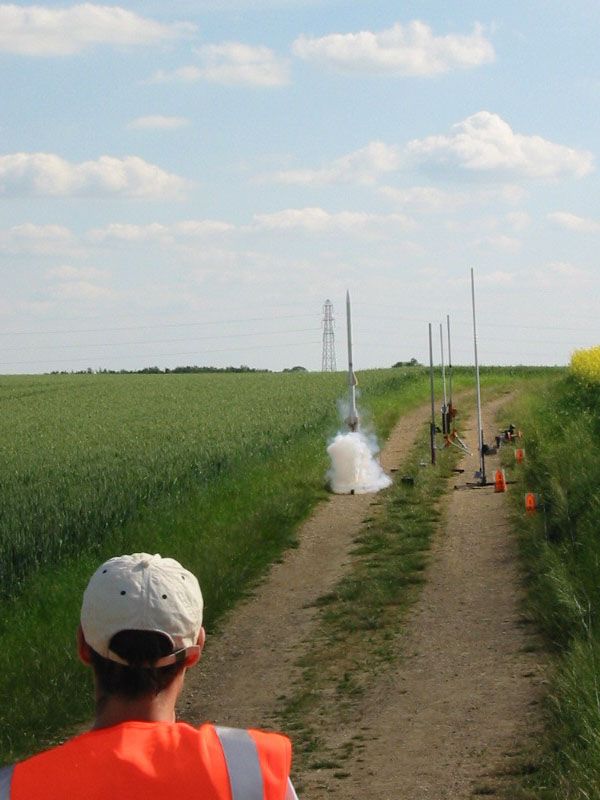
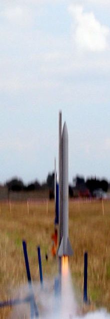
When it came to the flight, I took the rocket out to Gary Sinclair's 6ft rail, on a ‘Pete's Pad', and paused to take some photos before launch. Dave Warman RSO'd the flight, though I think my BP clusters alarm him somewhat after the flight of BlackJack at Big EARS (“The time of fear is upon us” was his comment before this flight IIRC!).
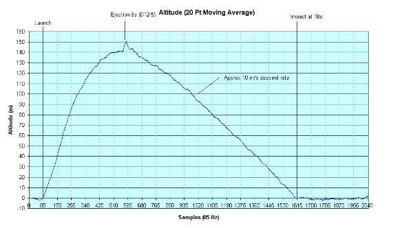
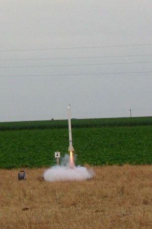
After the usual countdown, I pressed the button, and immediately the booster ignition bundle burst into a large cloud of smoke and fire, followed shortly afterwards by the whoosh of all 6 motors lighting simultaneously. The boost was good, with a slight weathercock, which can be seen from the photos. Shortly after booster burnout, the sustainer motors lit, and the ignition was spectacular – it stuck with me all day. The sustainer set off with a slight spin, and then coasted to apogee, deploying its 36” chute perfectly. Both stages had panic alarm beepers installed, and were easy to locate. However on recovery of the booster, the interstage bay and timer were missing, as was the pull-pin for the bleeper.
 |
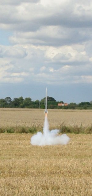
The moment of ignition - no sign of motors yet, this is just QM and slowburn going. Ignition was very fast and quite loud.
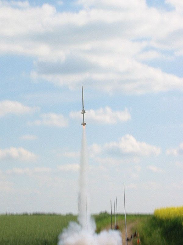 |
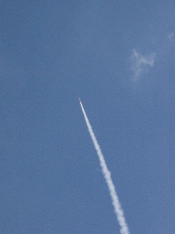
ETV2 leaves the pad with all 6 motors lit.
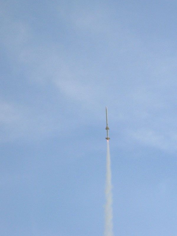 |
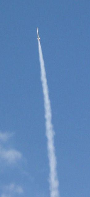
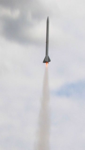
Hard to tell, but C11s may have burned out by this point.
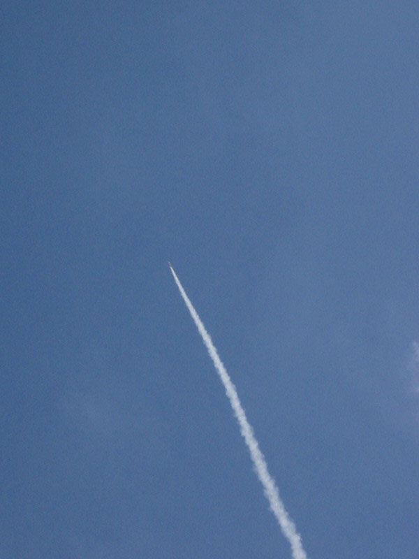
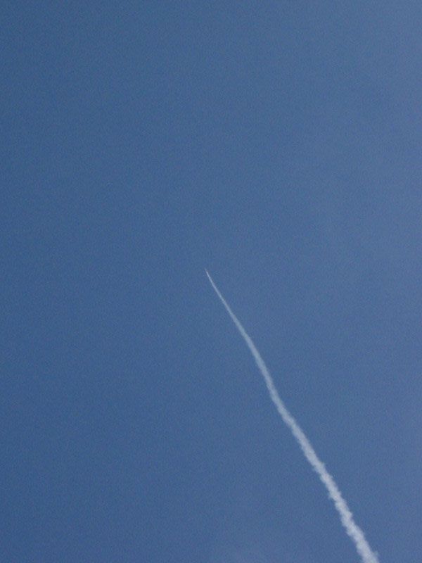
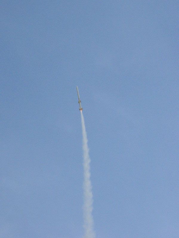 |
D12s still going.
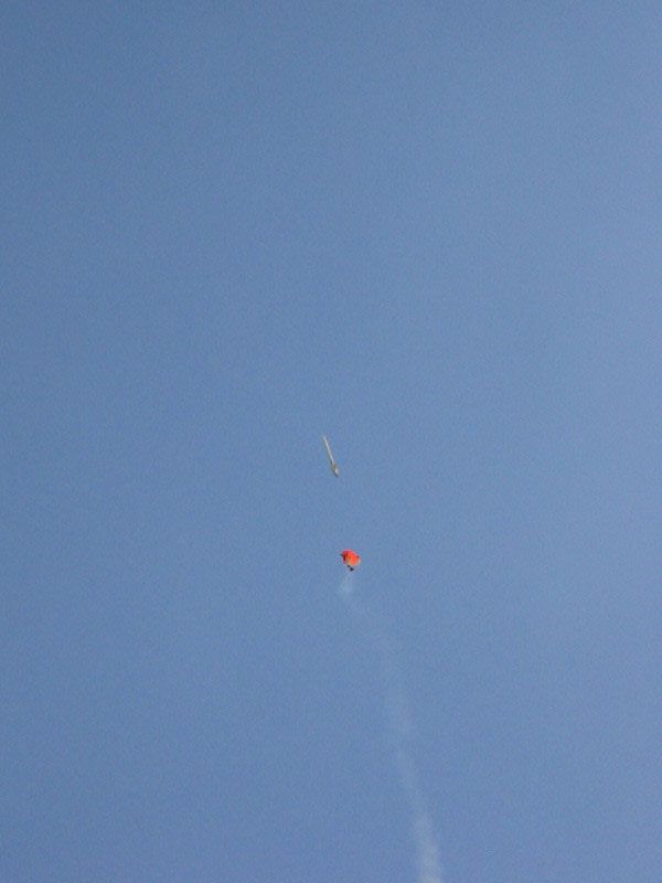 |
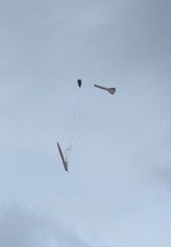
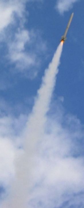
This is where things went wrong. The booster chute is out, and the sustainer is not lit. Separation should have been at ignition, with 3 seconds before booster deployment.
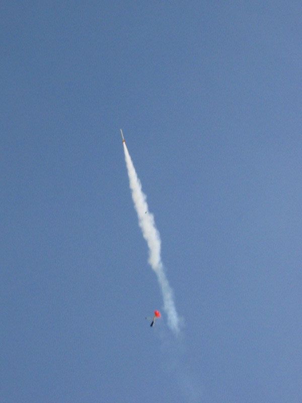 |
I didn't notice at the time, since this happened. The sustainer ignition was truly excellent, and the image stuck with me all day. Note the electronics bay falling in front of the smoke from the sustainer.
 |
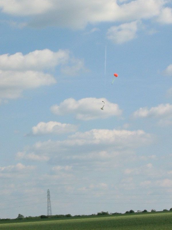
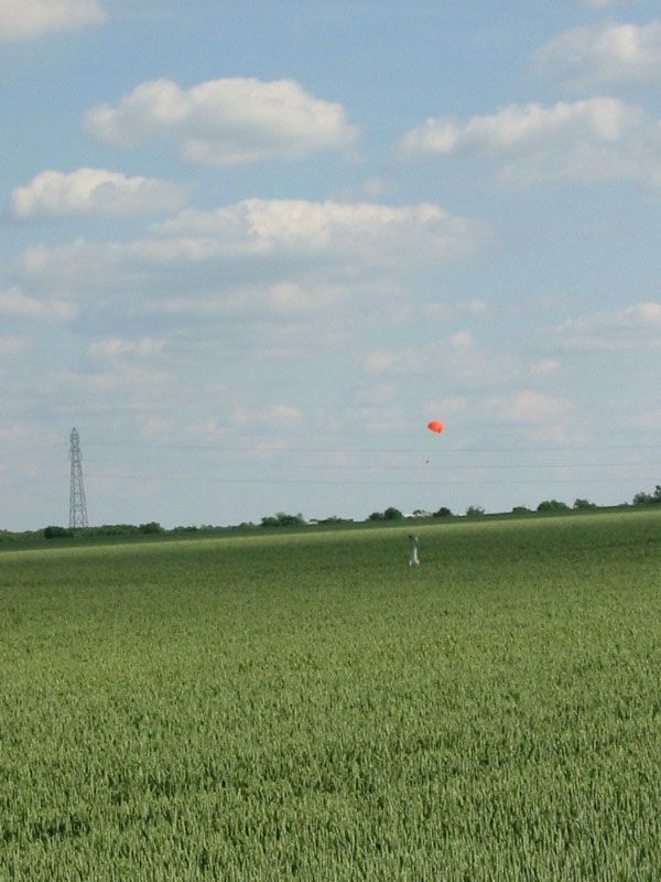
The sustainer flew perfectly, and recovered beautifully under a fully inflated 36" chute. Descent was very gentle, and the bleeper was audible from the moment of deployment until the moment I put the pin back in. They are truly essential in crops, and large parachutes certainly help too.
 |
 |
|
Booster chute properly out, but by the looks of things it was tangled up by the open end of the booster airframe, and was hit by both ejection charges. It now has two spill holes...
|
What went wrong?
On first appearances, it looked like drag separation, which seemed plausible since the booster has 6 large fins and two outboards. However, I'd made sure the connection between the electronics bay/interstage was tight, with tape on the coupler. Whichever way, I was lucky that the electronics bay stayed coupled to (what is left of after UKRA) the rear of the sustainer. The electronics functioned perfectly, but then fell into the field, and was seen by several people. However, following recovery of the booster and sustainer, several searches of the area turned up nothing. The timer was set to beep continuously after staging, but when inside the bay, the beeps were very quiet, and the battery may have been dislodged. Much careful listening out in the field came up with nothing.
The crops in the field were very dense, so it would have taken a stroke of luck to find the timer, it is fortunate that it was able to ignite the second stage, or I would have been searching for the remains of the sustainer much further out, and could have lost the whole lot.
On removing the spent motors, my personal suspicion was confirmed - both the 'plugged' D12s had blown straight through the epoxy caps I'd created. I used 5-minute epoxy, and I don't think I mixed it in quite the right proportions, since it was still a little tacky (whereas, by chance, the two in the sustainer had both set rock hard). I had discovered after the flight that R+T did have D11-P's, if only I'd bought a packet I would probably have my electronics back. However this gives me the chance to re-design the PCB for a better fit, and has taught me several useful lessons.
Despite the loss of the electronics, it was a truly excellent flight, and not one I will forget in a hurry. The upper stage ignition is probably my personal favourite rocketry moment so far, and will take some bettering.
After this flight, I made a pair of new timers, with a longer, narrower design to make fitment easier. I also set about painting the rocket, but as I write this the rocket is yet to fly in anything more than primer!
Flight No. 4
At July's EARS launch, I put up ETV2 on 4 D's again, flying the sustainer alone. The flight was good, but deployment was a little early. The plugged motors were D11-P's and remained plugged, so it must have been a bonus ‘short' delay on either the D12-5 or D12-7 I used for deployment. Recovery was good, with the rocket floating gracefully down to land a few hundred yards away, just into the rapeseed. No damage was sustained, and the ignition bundle made a nice cloud of smoke since it was ‘augmented' with a little pyrodex. I didn't get the best photos of this launch, but Rod Stevenson got a good video, which I will obtain a copy of at some point (after DESCON I expect).
Flight No.5
Having been rather busy with various things – exams, band tour, work, L1 project – ETV2 has had no attention over the summer. However it had suffered no damage so when the Canterbury Cup/Heckington Mug came around, and I couldn't fly my L1, I had something of reasonable size to fly. I managed three flights over this two-day event, all of which went well.
The first flight was on 2 D11-P's and two D12-5's lit with quickmatch as ever. Ignition and boost was good, and on this flight I noticed quite a pronounced spin to the flight. However at ejection, the parachute remained inside the body tube, and the landing was harder than I would like. The rocket sustained a slight crease in the sustainer body tube, but nothing major.
Flight No.6
For this flight, I set the rocket up in the same way as the previous flight, with the exception that one of the plugged motors was a D11-P and the other a plugged D12-0. For this launch I had someone else press the button, while I stood closer (the controllers were set up 100 yards away for HPR flights) to get some good photos. On this flight, I had changed the parachute for a smaller nylon chute – a rocketman type design that came with my L1 kit – about 24”. Ignition from close-up was quite impressive, and did yield some good shots. However only three motors lit again, with the culprit being another clay-filled D11 nozzle. Recovery was close to the pad, feet away from a water-filled ditch, which I am very glad the rocket avoided. The only other negative point was that the beeper failed to activate, after I had re-rigged it and managed to tape the pull-pin in – duh! Aside from that another good flight – I like BP clusters!
Flight No.7
This flight is probably my second favorite flight on this rocket after the two-stage flight. I loaded up the rocket with 2 E9-P's and 2 E9-8's, and the usual quickmatch bundle. For this flight, Andy Moore pressed the button while I again stood closer and took photos, which came up with some good results. The boost was really nice, with the 3 second burn on the E motors seeming to last much longer. Ejection looked pretty much spot on, but again the beeper didn't activate. Thankfully the rocket was visible all the way down, but ended up much further away, two fields away. The red chute was sat on top of the crops, so finding the rocket was easy. I was very pleased with this flight, and I want to repeat the 4 E's flight at the next launch, its definitely a good motor and rocket combination. Also good would be to fly with 6 D12's in the booster and 4 E9's in the sustainer, but this would be into ‘H' impulse – about 220 Ns.
 |
 |