Descon 8 F.T.B.o.D. Original Design / Scratch Built
Scratch - F.T.B.o.D. {Scratch}
Contributed by Mark Simpson
| Manufacturer: | Scratch |
 |
|
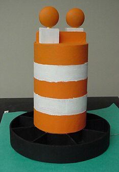
| F.T.B.o.D. by Mark Simpson As part of my Level 3 project, building and flying a full-sized orange traffic barrel, I decided to make a 1/6th scale flyable traffic barrel to test its dynamic flight stability. I started with a 3" section of garden variety mailing tube, donated by an office mate. I scrounged a piece of 6" mailing tube from another office mate to use as a larger ring fin. Since the "real" traffic barrel, purchased for the L3 project, was sitting in my garage already, I got out my tape measure and went to town taking measurements. Here's a summary of the major dimensions:
Now that I had the basic dimensions, I went to work creating the model. Here's a materials list:
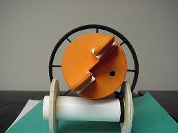
I started by cutting 6" of 3" mailing tube on my Miter saw, then cutting a 1" ring off of a 6" mailing tube, using an Exacto knife. Using VCP I printed out a fin alignment guide using the following information: I laid the 3" body tube on the alignment and positioned the 6" outer ring so that the radiating lines from alignment guide were even all the way around the ring. This ensures that the 6" ring fin is equidistant from all points. I then marked the inside of the radiating line so that I could measure the length of balsa needed to act as supports for the ring fin. (It was slightly less that 1.5") I cut out 8 supports from scrap balsa that were roughly 1.5" X 1", making sure that the grain was perpendicular to the body tube. I test fitted the 8 supports inside the ring fin, while sitting on the fin alignment guide. After some minor adjustments and sanding, I glued all 8 supports in place. (Getting them straight was easy since I glued them on top of the alignment guide.) Once dried, I filletted all joints to add strength and removed the assembly from the guide. The motor mount assembly is made from a small piece of 29mm motor tube ~5" and balsa for centering rings. To strengthen the centering rings, I made four and glued them in sets of two with one of each pair having it's grain perpendicular to the other for strength. I glued both ends on and drilled a hole to pass the shock cord through.
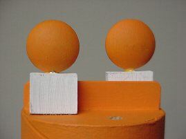
Now comes the shock cord attachment and weighting process. I used a small screw eyelet and screwed it into a _" by _" block of plywood which I glued into the underside of the basswood barrel top (see photo below) Then I added a _ thick plastic spacer from a brown paper roll endcap and punched out a section so that the launch rod could go through the rocket. I filled the _" circular gap with a mix of modeling clay and steel shot (estimated at ~2-3 oz). Attached to the eyelet was a stainless steel wire fishing leader. I tied the other end of the leader to 3' of heavy duty nylon shoelace.
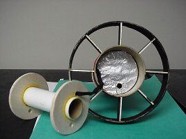
The shoelace is attached to the motor tube assembly. The aluminum foil-covered disk in the picture below is to protect the shockcord and upper portion of the barrel's insides. Since this is a rear ejection model the whole motor assembly should fit loosely in the body tube. The parachute is wrapped around the motor tube ( like in the Estes Sizzler). Care should be taken when test fitting the assembly so that holes can be drilled to allow the launch rod to pass through the rocket.
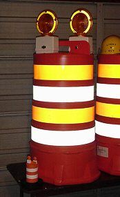
Since this was to serve only as a test vehicle for the real thing, I painted the rocket using water-based acrylics. The completed project is below.
Flight Report: |

 |
 |