| Manufacturer: | Scratch |
 |
 G-Whiz |
|
|
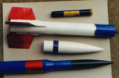
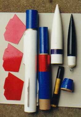
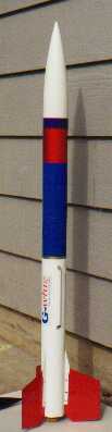
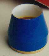
G-whiz Overview: G-whiz is a LMR/MPR/ low end HPR 3FNC/Payload design with one good idea at each end. It was intended to be a testbed for an as-yet unbuilt rocket called I-whish ('cause I wish I could afford to build it now), but two ideas define the design for me: Replaceable fins and a double-wall payload section that extends forward into the hollow plastic nose cone. Being able to replace the fins means: (1) you can change the shape, size, and material, either to experiment, or to suit the payload and motor combination, or just for looks; (2) the rocket packs for storage and transport in a much smaller box; and (3) the fins are anchored to the inside of the body tube; the fin mounting pylon doubles as a gusset for the motor mount, and is epoxied to the MMT, the airframe tube, and the forward and rear centering rings for a rock-solid motor mount. Double-wall payload construction means: (1) A cozy, well-protected environment for electronics or other payload; (2) payload tube extends into hollow nose cone, shifting weight and capacity forward into otherwise wasted space; and (3) adjustable ballast can be placed far forward in the nose cone, requiring less than if it were attached at the base, and safer than if it were cast into the tip. (4) The real reason I did it, though, was to adapt to an electrical staging arrangement in a project I call Hop on Pop -- which, when it flies, will launch a tiny dartlike sustainer powered by an Apogee B2-9. While G-whiz was envisioned for the AeroTech G40-7 motor, it is HPR capable and its first flight was a perfect one with H238T-M(10). G-whiz is not related to the Pratt Hobbies altimeter called G-wiz, though it may someday use one. |
|
Parts and Materials Fin Material Selection: My fins are made from 1/16" fiberglass printed circuit board (PCB) material, which I bought from an electronics surplus outlet. The copper can be etched away using Ferric Chloride etchant available at Radio Shack, which also sells sheets of PCB if you can't buy it as junk. The other basic option is 1/8" aircraft plywood. Pylon and Fairing Cores referred to below can be of any material but must be at least as thick as the fin. (If you use a fin thinner than your pylon core, it can be shimmed.) Pylon and fairing shells are 1/16" plywood which can be reinforced with fiberglass if desired. Remaining parts list: Five minute epoxy, yellow glue, and/or C/A for quick assembly; 15 min. or 30 min. epoxy for fillets; razor saw; hobby knife; sandpaper; vise or clamps; approx. 6" piece of metal angle stock; hack saw and file for cutting fiberglass sheet. |
|
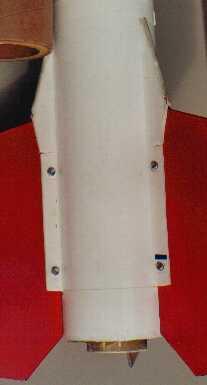
G-whiz Construction: Fin and Motor Mount Assembly (1) Begin by preparing individual parts. From the two 2.14" o.d. couplers cut three pieces: 1/2", 3" and 4" long (to match prototype; the 4" piece could just as easily be full 6"). Epoxy the two 1.14" centering rings flush with one end of the 1/2" and 3" pieces, working epoxy into the end layers of the coupler as you do so. Refer to the pattern layout and cut out pieces as follows: Three fins from your chosen material; three pylon cores and three fairing cores from balsa or plywood stock at least as thick as the fin; six pylon shells and six fairing shells from 1/16" plywood. Stack all six pylon shells, clamp together, and drill the two holes shown on the pattern, using a 1/16" drill. The 2mm screws will thread through these but not slide through. Assemble the three fairings and the three pylons using 5 min. epoxy, yellow glue, or C/A. I used yellow glue and clamped each set between two blocks of wood until dry. If you glass the pylon shells, you will need to assemble them with epoxy. Mark the main booster tube for three fins. Make an additional mark clockwise from each mark by the thickness of the assembled pylons. Mark 1" and 3.75" from the aft end of the tube. Using the metal angle as a guide/ruler and a very sharp hobby knife, cut the three slots, which will each be 2.75" long, either 3/16" or 1/4" wide, and 1" from the aft end. Clean up the edges of the cut slots, especially inside. Following steps will be easiest if each pylon fits just snugly enough in a slot to hold its place while you work. |
|
|
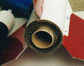
(2) Test Assemble the motor mount and fin canister. Slide the 3" coupler into the tube from the front, centering ring aft. Fit the three pylons through their slots from the inside, sanding the shoulders of the pylons as needed to make them sit squarely in position. Push the coupler down against the pylons from the front. Test-fit the 2.14" i.d. x 7.75" motor mount tube through the pylons to and through the centering ring, and then slip the short coupler and ring assembly over the MMT and into the aft end of the main tube. You want all three pylons to rest against but not dent or damage the MMT. Carve or sand until this is the case. The short coupler should be flush with the aft end of the body tube. Remove everything (except the 3" coupler may be left inside the forward part of the tube; move it several inches out of position). Note and mark which pylon fits which slot; they are unlikely to be identical. Place the aft centering ring assembly (with 1/2" coupler) ring side up. Drill two 1/4" holes in the plywood ring, on opposite sides, so that the holes just touch the cardboard coupler at the outer edge. Test fit the T-nuts, then epoxy them into place from the centering ring side of the assembly. (3) Final assemble the motor mount and fin canister. Put a dab of 5-minute epoxy or yellow glue on the "shoulders" of one pylon and glue it in place from the inside of the tube, aligning it carefully. When it has set, use a dowel or stick to generously spread slow-cure epoxy in the area where the 3" coupler will rest; push it down into position, pausing when it is a half-inch from the pylon. Use the stick to spread epoxy generously on the face of the centering ring, being careful not to get any on the inside surface of the ring; they fit quite tightly as it is. Now push the coupler down against the first installed pylon. Again using the fast-curing epoxy (C/A if you prefer) tack the other two pylons in place. When the fast-cure epoxy is quite tacky but preferably still flexible, install the MMT to the forward centering ring by coating the outside surface of the tube and pushing it in from the rear. Be sure the coupler stays in place against the forward end of the pylons! Hold the MMT in place with the aft centering ring, but do not attach it yet! Push the MMT forward until it projects from the aft end of the body not more than 3/8". Adjust everything for best possible alignment and allow it to cure. Remove the aft centering ring assembly. With a dowel or other stick, fillet the pylons inside the main body and at the MMT. It helps to do one of the three cells at a time. When all fillets are firm, apply epoxy around the inside lip of the body tube and to the aft ends of the pylons; press the aft centering ring assembly in place. Allow to cure.
|
|
(4) Shock Cord Mount. Note: this describes the system in place in my prototype, which uses braided elastic for the shock cord. If you use tubular nylon it might be better to epoxy the end of it to the inside of the 3" coupler before installing that; in this case, omit the plywood bulkhead. This would have the added advantage of allowing a longer motor casing such as the 29/240. The 2.14" plywood bulkhead disk gets three holes: a 3/16" hole in the center and a 1/2" hole on either side of it. The two larger holes are to pass ejection gas and should be out toward the edges of the disk. One of the eyebolts goes in the center hole. Put a nut on the eyebolt, then the disk, then a washer, then another nut. Coat the nuts, bolt threads, and washer with epoxy and cinch down the nuts on both sides of the bulkhead. Epoxy this to the forward end of the 3" coupler which you installed earlier as part of the motor mount, with the eyebolt facing forward into the recovery bay. Fillet the edges of the bulkhead with slow-cure epoxy. (5) Fin Fairings Sand the leading edge of each fairing assembly round. Test-fit the fins and be sure each fin will sit firmly in one of the pylons. Mark them, if necessary, to assign one particular fin to each pylon. With a fin in place, test-fit a pylon to the front of it. The tabs on the fairing shells should just touch the tabs on the pylon shells. Trim or sand as necessary for best fit. Glue/epoxy the fairings to the BODY TUBE ONLY, not to the fin! You may wish to tape the fairing shell tabs to the pylon tabs while glue dries. When dry, remove the fin and fillet the fairing and fin pylon tabs with a single application of epoxy. At this point I also worked a coat of epoxy into the entire surface of the fairing, especially the leading edge. Allow to cure. Re-install each fin and mark with a pencil where the screw holes will be. Drill slightly larger holes in the fins: I used a 3/32" bit. Now you can test fit the nuts and bolts. (6) Launch Lug Prototype's 1/4" i.d. x 6" long launch lug is centered between two fins but farther forward, with the aft end about 2" forward of the tips of the fin fairings. Since the CP (as drawn) is near the forward tip of the fairings, the rocket will be stable if the balance point (CG) is within the length of the launch lug. If you prefer, you can use two short lengths of launch lug, one at the aft end of the body and the other anywhere forward of the CG. |
|
Additional Details: (9) Motor Retention: "Kaplow Klips" can be anchored in the T-nuts described earlier, or the motor can be taped to the aft end of the MMT. I have done both on this rocket. (10) Parachute Size RockSim specifies a 34" parachute for this rocket, which will not fit in the recovery bay unless you modify the design by extending the body at least 4" (which will not hurt it, btw). Three flights, however, confirm that a 20" hemi cloth chute is adequate and does fit. (11) Mods, or "what I would do if or when I do it again:" Some are mentioned above. a. Body tube length: Originally both main body and payload were set at 15.25" for no better reason than the rocket, disassembled, would fit in my briefcase. I added 3.5" when it obviously needed more parachute space, giving up the briefcase idea. In hindsight I would have made the main body about 24" long. This will move both the CP and CG forward, but will not hurt the design overall, and would facilitate use of the 29/240 hardware. b. Fin thickness: My fins are 1/16" thick, and only the fiberglass ones are strong enough at that thickness. I suggest in the instructions above making the fin mount cores 1/8" thick. PCB fins would still work with shims. c. Inside bulkhead and shock cord mount: The bulkhead in the prototype was part of a baffle arrangement that did not work. The centered eyebolt works well with my elastic shock cord. However, if I started today I would omit the bulkhead and use a tubular nylon harness with the end epoxied to the inside surface of the coupler before assembly. d. Reinforcement: I would suggest laminating the pylon shells with a layer of 2oz fiberglass before assembly, and also laying a covering of fiberglass over the fin fairings after assembly. In case you wondered: The blue-bordered picture you see at top left is the second flight of Gwhiz, about an hour
after the first. It had a different set of fins and the 1.52" nose cone, which made it look quite different. The
photo taken in my living room has yet another set of red fins, which I haven't used in flight because they're the same
material as the ones that shredded. |
|
gwaft.jpg gwapart.jpg gwdetail.jpg gwtall.jpg gwtrans.jpg |
 |
 |