| Manufacturer: | Scratch |
Heavy Lifter
An RMR Descon XIV entry
by David Fergus
(Place your mouse over photos to view the captions.(IE5))
 Design
Summary:
Design
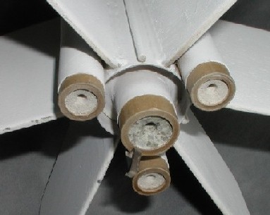
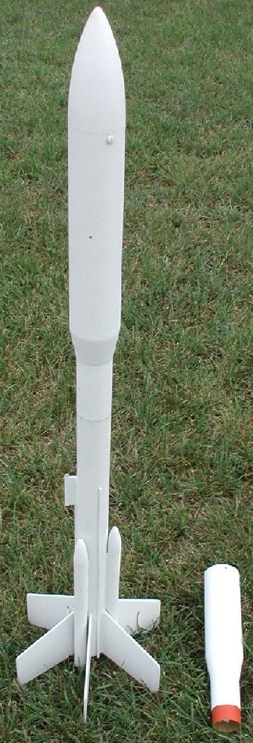
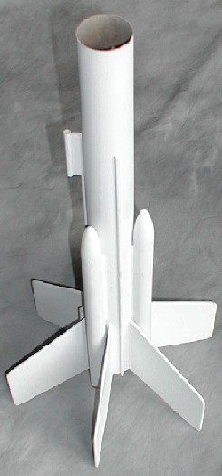
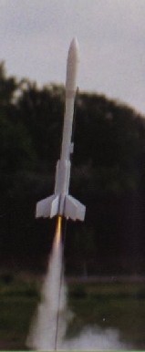
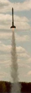
Summary:A four engine cluster rocket with two optional payload bays. One central D engine mount and three side pods for optional C engines that rear eject. The rocket has six fins and split recovery of the lifting body on one chute and the payload section on another chute. The main body is BT-60 and the payload bay is BT-70. The C engines are rear eject and can be either B or C6-0. Because the side motors are ejected while hot, this rocket should only be flown in a cluster configuration where no danger of fire exists, like a sod farm. The model weighs 8.3 oz. with empty payload and no engines. With a full payload of 6.7 oz., one D12-3 and three C6-0 engines, and two parachutes, the fully loaded model weighed 20 oz. The empty booster weighs 5 oz. and the larger empty payload bay weighs 3.3 oz.
Aspects new to me that required a developmental learning process:
1. reliable ignition of four engine clusters. (I had never done clusters before.)
2. four engine cluster with smaller engines in the side pods. (flight/fault issues)
3. electronic payload design and usage. (I didn't even own an altimeter before.)
4. rocket stability with a large payload-weight/total-lift-weight ratio of 1:3.
 CONCEPT:
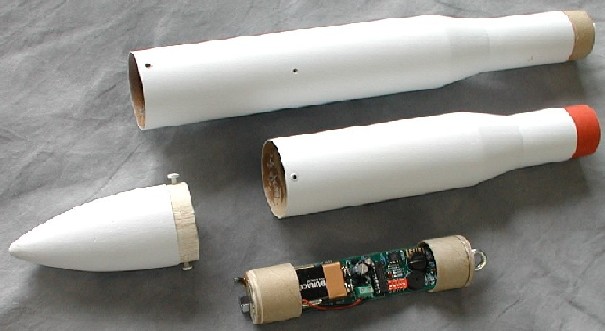
This rocket began as a concept after obtaining some out of production balsa at a hobby shop going out of business. I obtained one balsa BT-70 nose cone and two BT60-70 balsa transitions. I then began to think about how I could use them. After getting some BT-70 body tube from a friend (Damian Kostron of KosRox), the idea began to take shape of a Delta-like payloader. It grew into a D engine BT-60 central booster supported by three BT-20 C engine side boosters carrying a BT-70 payload section. Not having any method to calculate stability of such a complex shape, and knowing it could be carrying significant weight, I guessed and built it with six large through-the-wall fins. When first built in 1999, I had no experience with clustering and electronics, so an extensive test program and developmental process was necessary. Therefore, I include flights of other rockets as part of this project that verified I could accomplish objectives prior to the full up final flights. Except for internal hardware such as engine hook, nylon nose cone attachment screws, and screw eyes, the model is all wood and paper construction. I place high value on RMR Descon entries that teach me design and modeling techniques, so I attached the nose cone to the payload the same way the winner of Descon 4 did it on the Lego-13 with nylon screws and CA. I lost the original nose cone to my vintage Estes SAROS because it was not attached firmly enough to the payload body tube, so I am very sensitive to ensure secure attachment of nose cones to payload bays. The MissleWorks RRC2 altimeter was obtained late in the program, and the original payload bay was discovered to be too short. Therefore, a second larger payload bay was built with the second balsa transition to accommodate the altimeter. The shorter payload bay is used for smaller/lighter payloads. The rocket can be flown with a single D engine or with a cluster of one D and three C-size engines.
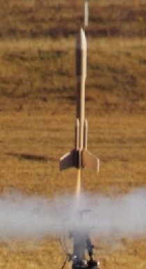
CONCLUSION/RESULT SUMMARY
After eight flights of the Heavy Lifter and several flights of other rockets, I consider the project a success. I have successfully demonstrated reliable cluster flights with different engines in the same cluster. I have successfully demonstrated use of electronics to measure altitude. I have successfully designed a rocket capable of reliably lifting a payload 1/3 of the total rocket weight including engines. On it's eighth flight, Heavy Lifter flew to 490 feet on one D12 and three C6's. It was carrying a payload weight of 6.7 oz. and recovery was perfect with no damage! My next venture is to build a rocket that actually uses the full capability of the RRC2 altimeter/controller.
Materials
BT-70 body tube
BT-70 balsa nose cone
2 balsa BT-60/70 transitions
BT-60 body tube
3 BT-20 body tubes
3 BT-20 balsa nose cones
balsa fin stock
D engine BT60 heavy duty engine mount with hook
2 BT-60 couplers
2 metal screw eyes
3 heavy duty 18mm engine blocks
Pratt small braided Kevlar shock cord material
Elastic shock cord material
2 Nylon screws
wooden dowel
parachutes from other kits as appropriate for weight
Construction
Main Engine Mount:
Build a standard D engine mount for placement in a BT-60 body tube. Leave room for 2 inches of through-the-wall mounting of fins to the engine mount. Use an engine hook and a heavy duty thrust ring.
 Main Booster Assembly:
1. Using a hard grain 1/8 inch balsa, cut six fins with the lead edge going with the grain. Specifications on the fins are as follows: root edge is 4 inches, tip edge is 3 inches, lead edge is 4.75 inches and the trail edge is 4 inches. There is a 2 inch long through-the-wall piece that glues to the BT50 tube in the engine mount. Sand and prep as desired.
2. Cut a section of BT-60 to 18 inches. Glue the engine mount into one end so that 1/2 inch of the mount extends past the end of the BT-60 tube. Measure and mark the tube for 6 fins and six attachments equidistant from each other on the tube. 3. Cut six slots for the fins to mount to the engine mount. Glue and attach the fins. Apply the glue fillets before installing the side tubes.
4. Cut three lengths of BT-20 to 9 inches (or longer if desired). Glue balsa BT-20 nose cones into each of the tubes. Sand and prep as desired. Glue heavy duty thrust rings into the other end of each of the tubes so that 1/4 inch of motor will stick out.
5. Because the launch lugs are on the booster and the launch rod needs to clear the wider payload section, the launch lugs need to be installed on extension pieces. Cut two 2 inch lengths of 3/16 inch launch lug. Cut out two pieces of 1/8 inch fin stock into a rectangular shape 3/8 inch x 2 inch long with the grain going with the short edge. Glue each launch lug to one of these extension pieces. On one of the alignment lines, glue each of these launch lug sub-assemblies on the rocket body 1.5 inch from the rear and 6 inches from the front as measured to the rear of the sub-assembly. Make sure they stay aligned until the glue is set.
6. Cut out a section of 1/8 inch dowell and glue on the line between the two launch lug assemblies. Cut out two more pieces of dowell at 14 inches, cut an angle on one end of both of them, and glue to the corresponding aliignment lines so that the three dowels are 120 degrees apart.
7. Glue the three side boosters onto the main booster along the remaining three alignment lines so that 1/2 inch of the rear of the tube extends past the end of the main tube. Apply glue fillets and sand and prep as desired.
8. Epoxy a 12 inch length of small or mini braided tubular Kevlar (available from Pratt Hobbies) into the inside of the main booster tube. Tie a small loop in the loose end and epoxy the knot. Leave at least an inch of clearance for the tube couplers of the payload section. Tie a 2 foot section of 1/4" elastic shock cord to the kevlar loop. Tie a loop in the other end for parachute attachment. Put a spot of glue on the knot.
9. Fill in grooves and fillets with Elmers FF as desired, and sand and prep.
Payload Section:
1. Cut a short 2 inch piece of BT-60, and glue in a coupler on one end.
2. Install an eyehook in a balsa BT60-70 transition, secure it with glue. Attach a two foot section of 1/4 inch elastic shock cord. Put a spot of glue on the knot. Tie a small loop in the other end of the shock cord and put a spot of glue on that knot.
3. Glue the balsa transition into the short piece of BT-60.
4. Cut a length of BT-70 anywhere from 6 to 10 inches long. The length of this piece depends on the size of the payload you anticipate using. In my case, I guessed wrong and had to build a second payload section to accomodate my altimeter and its multi-functional housing and adapters.
5. Glue the BT-70 piece on the top of the balsa transition.
6. Drill two small 1/16 inch holes on either side of the payload bay for altimeter pressure sensing. Apply some CA to the holes to strengthen and prevent fraying of the edges with use. Sand to smoothness, both inside and out.
7. Apply CA to the edges of the payload section to a depth of about 1/2 inch. Sand until smooth. This step is to strengthen the edge of the cardboard and prevent fraying with use.
8. Install the nose cone and hold securely while drilling 1/32" holes suitable for the nylon holding screws. Then remove the nose cone and drill larger holes in the walls of the payload bay with just enough clearance for the nylon screw threads. With the nose cone removed from the rocket, work in threads into the balsa nose cone using a metal screw of the same thread as the nylon screws. After the threads are well defined, drop some thin CA into the holes and quickly work the metal screw in and out once to coat the thread surfaces with CA. Then after the CA has cured, work the threads again with a metal screw until it threads smoothly. Then install the nylon screws to make sure they work smoothly as well. Repeat this process until the the nylon screws twist smoothly, and securely hold the nose cone to the payload section. This method of nose cone attachment was learned from the winner of DESCON 4 with the LEGO-13. This method should allow easy removal and installing of the nose cone while on the flight line to minimize time an altimeter is energized if using one as a payload.
9. Fill in any grain and spirals with Elmers FF and sand as required. Keep the drilled holes clear and open for pressure equalization.
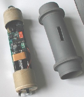 Altimeter Mount:
Since the RRC2 altimeter and it's custom retaining module with on-off switch was designed to fit into PML 38mm phenolic tubing as well as thinner Estes BT-60, an adapter was necessary to securely keep this particular payload load from rattling around. An adapter was built out of extra 38mm engine tube and two plywood adapter rings. Slots were cut for pressure equalization. This adapter could be used for payloads other than altimeters as well. The altimeter payload was heavier than it needed to be for several reasons. I wanted to challenge my Heavy Lifter with a lot of weight, but also have a retaining system I could use in later complete uses of the altimeter for dual deployment of bigger rockets, etc. The Heavy Lifter was designed to lift heavy loads and this altimeter package just happened to be a convenient one; and also as a byproduct get an altitude readout of flights.
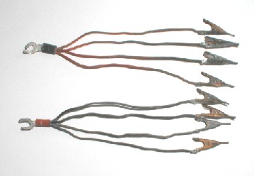 Cluster Igniter Clip Whips:
I used 18 gauge solid copper wire with high temperature insulation. I made one clip whip with red insulation, and one clip whip with black insulation. Cut four six inch lengths of each color. Strip the insulation on both ends of each wire. Install four red wires and four black wires each into a connector and crimp. Conduct a pull test to ensure reliable crimp and then solder the joint with high temerature solder. Obtain eight copper flat clips, and connect each clip to a wire end with high temperature solder. Do a pull test and then an impedance/resistivity check to ensure the solder joints are good.
Flight NOTE: The red and black wires are necessary to distinguish between leads while hooking up to igniters. One black and one red lead goes to the two leads of an igniter for each engine. You must also be very careful to not allow any clips to touch any other clip or exposed wire, or incomplete ignition could be the result!
Finishing:
The rocket was painted a base coat of Krylon gray primer, sanded then painted several coats of Krylon flat white, which was the coat of paint on most intermediate flights. Finally, the rocket was painted gloss white. Decals are pending. Just a few decals add a lot to appearance.
Sequence of Results/Flight Details
 1. 11/20/99 - (FLIGHT
1,2) The original rocket was built and first flown unpainted with an empty
payload bay and then a second time with 3 oz. of weight in the payload bay. A
single D12-3 motor was used for both flights. These two flights were successful
and demonstrated excellent flight stability and recoverability. The
�" shoulder of the balsa transition BT60/70 was too wobbly on the
booster section. A correction to this problem was identified to lengthen the
shoulder by adding a short piece of BT60 with a standard coupler to the payload
section.
1. 11/20/99 - (FLIGHT
1,2) The original rocket was built and first flown unpainted with an empty
payload bay and then a second time with 3 oz. of weight in the payload bay. A
single D12-3 motor was used for both flights. These two flights were successful
and demonstrated excellent flight stability and recoverability. The
�" shoulder of the balsa transition BT60/70 was too wobbly on the
booster section. A correction to this problem was identified to lengthen the
shoulder by adding a short piece of BT60 with a standard coupler to the payload
section.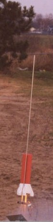 2.
5/21/00 - (FLIGHT 3,4) After a 4 inch piece of BT-60 was added to the bottom of
the payload section with a tube coupler, the rocket was painted a base coat of
white and again flown twice carrying 3 oz. of weight in the payload bay and
boosted by a single D12-3 motor. Winds were brisk gusting to 15 knots. The
wobble problem was corrected, but the parachute got jammed up in the new
section and the payload section tumble recovered. The additional section of
BT-60 on the bottom of the payload section was deemed to be too long and
allowed the parachute to bunch into this area and not deploy. The BT-60 portion
of the payload section was shortened to 2" and a new coupler installed.
2.
5/21/00 - (FLIGHT 3,4) After a 4 inch piece of BT-60 was added to the bottom of
the payload section with a tube coupler, the rocket was painted a base coat of
white and again flown twice carrying 3 oz. of weight in the payload bay and
boosted by a single D12-3 motor. Winds were brisk gusting to 15 knots. The
wobble problem was corrected, but the parachute got jammed up in the new
section and the payload section tumble recovered. The additional section of
BT-60 on the bottom of the payload section was deemed to be too long and
allowed the parachute to bunch into this area and not deploy. The BT-60 portion
of the payload section was shortened to 2" and a new coupler installed.
3. 6/23/01 - (FLIGHT 5) One flight on a D12-3 to confirm reliable parachute deployment. Confirmed, and developmental program fully approved for next steps.
4. An RRC2 altimeter was obtained as a birthday present from my wife, and a custom holder was designed and built for a 38mm payload bay.
5. 11/17/01 - The Tri-Stomp (my Descon 9 entry) was designed and built specifically for testing and learning how to do cluster rocketry. The foam boink recovery method was deemed to be safe for developing this new skill set. Also, the rear engine eject system of Tri-Stomp would be the same as the side booster pods on Heavy Lifter. Tri-Stomp was twice successfully launched on three B motors with all three motors lighting both times, once at a club launch using the club launch system, and once using a truck battery and my own launch system. A set of 4-engine clip whips was constructed for this program and general use.
 6. 5/18/02 - (FLIGHT
6) Heavy Lifter flown on 4 engine cluster with short payload bay and 3 oz. of
payload weight. (one D12-3, three C6-0's) The shortened coupler section of the
payload section reliably deployed the parachute, while maintaining a stable
connection to the booster section during flight.
6. 5/18/02 - (FLIGHT
6) Heavy Lifter flown on 4 engine cluster with short payload bay and 3 oz. of
payload weight. (one D12-3, three C6-0's) The shortened coupler section of the
payload section reliably deployed the parachute, while maintaining a stable
connection to the booster section during flight.7. 5/18/02 - Altimeter tested in PML Cirrus Dart (an EMRR participation prize drawing give-away!). Rocket flew to 1069 ft on a G35W. This altitude was within the approximate estimated window of the Heavy Lifter altitude. The program is approved for the final steps.
8. 6/02 - 7/04. Program placed on development hold while project manager devotes more time to coaching his kid's sports teams, boy scouts, and being a soccer referee. The longer payload bay and altimeter adapter were constructed during this reduced activity period, similar to how a government program goes on hold for funding or other issues.
 9. 8/22/04 - (FLIGHT 7)
Heavy Lifter flown on 4 engine cluster with long payload and the altimeter
assembly. The altimeter assembly and adapter weighed 6.7 oz with a total rocket
weight of 20 oz. including engines. (one D12-3, three B6-0s). The wind was
gusting to 20 mph, so smaller booster engines were used to limit altitude. The
rocket flew to less than 300 ft. The Altimeter did not register a launch
(minimum of 300 ft in altitude required to register a launch). My eyeball
estimate of altitude was about 200ft. All systems operated properly including
the launch and recovery systems.
9. 8/22/04 - (FLIGHT 7)
Heavy Lifter flown on 4 engine cluster with long payload and the altimeter
assembly. The altimeter assembly and adapter weighed 6.7 oz with a total rocket
weight of 20 oz. including engines. (one D12-3, three B6-0s). The wind was
gusting to 20 mph, so smaller booster engines were used to limit altitude. The
rocket flew to less than 300 ft. The Altimeter did not register a launch
(minimum of 300 ft in altitude required to register a launch). My eyeball
estimate of altitude was about 200ft. All systems operated properly including
the launch and recovery systems.10. 8/22/04 - (FLIGHT 8) Heavy Lifter flown on 4 engine cluster with altimeter. (one D12-3, three C6-0's) One of the C engines lit before the other three and the motor burned for a second on the pad with not enough oomph to get the rocket moving before the others lit and the rocket lifted off. The rocket flew about twice as high as the previous flight. Ejection and recovery system deployment occurred at apogee. The booster section caught a thermal and drifted over the roof of adjacent apartment building (1/4 mile away). After recovery of the payload section and recording of altitude, the long walk found the booster section undamaged on the patio of an apartment on the second row of apartments into the complex (whew!). All systems performed properly, and all components were recovered with no damage. Altitude achieved was 490 ft as reported by altimeter. Unfortunately, no photographers were available for these last two historic flights.
 |
 |