Descon Lander (Spooge Prospector)
Scratch - Lander (Spooge Prospector) {Scratch}
Contributed by Kelo Waivio
| Manufacturer: | Scratch |
 Parts List:
(Note: a Fat Boy kit could be used for the stock parts of this rocket.
The parts listed are what I had on hand to use, but the Fat Boy parts look
like they'd work. I didn't want to break up the kit I had.)
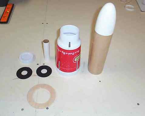
Found parts:
 click images to enlarge 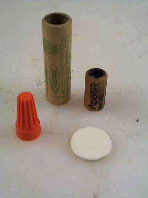 |
Stock parts:
|
 Depending on the cup used some dimensions or construction details may bhave to be altered.
Fit the BT80 over the bottom end of the cup and mark where the tube seats on one of the molded "rings". Cut off cup end at this point and test fit the body tube through the cup end. Save the cut off bottom cup to use later on. Cut a centering ring from the º" Balsa-Ply to fit up inside the large end of the cup. The cup I used had a shoulder about *" at the mouth and I cut the ring to seat on this shoulder. The ring is approximately 4 1/8" O.D.
Mark the cup outside for 4 fin slots. I started the bottom of the slot at the shoulder in the mouth of the cup just above the º" Balsa-Ply ring.. The slots are 3/16" wide x approximately 1 æ" long. Mark a spot midway between two fin slots and cut out a notch in the lower shoulder of the cup for the launch lug to slip through. (refer to photo) Cut a notch in the Balsa-Ply ring for the launch lug to fit through. Glue the 1/8" x 1/8" basswood strip to the body tube with the lower end about 3/8" up from the rear of the tube. Glue the launch lug on top of the strip. Cut the forward end of the LL at an angle.
Glue the Balsa-Ply ring onto the body tube by positioning the ring in the cup then fitting the tube into the ring. The tube will be aligned by the cup at one end and the hole in the cup at the other. Make sure the notches for the LL line up. After the glue sets you can glue the whole tube/ring assembly into the cup. I used epoxy for the balsa to cup joints and Tite-Bond for the paper, basswood and balsa joints.
 The fin/legs were cut from 3/16" basswood. The edges were rounded over
slightly. Legs were glued onto the body tube with epoxy. Medium CA
was used between the legs and the edges of the slots. The 1/8" x 3/8" strips
were cut to length, ends at an angle. These were attached to each side
of the legs with medium CA. The gap between each leg "track" was filled
with the 3/16" x 3/16" balsa strip cut to fit.
The fin/legs were cut from 3/16" basswood. The edges were rounded over
slightly. Legs were glued onto the body tube with epoxy. Medium CA
was used between the legs and the edges of the slots. The 1/8" x 3/8" strips
were cut to length, ends at an angle. These were attached to each side
of the legs with medium CA. The gap between each leg "track" was filled
with the 3/16" x 3/16" balsa strip cut to fit.
The clay nozzles of both the 13mm Estes and 10.5mm Apogee engine casings were drilled out. The 10.5mm æ" long casing sections are glued into one end of each 13mm casing º" deep using Tite-Bond. Epoxy was used for the wire nuts. The 20-50 paper ring centers were glued up in pairs with Tite-Bond then glued to the ends of the spent casings. Each pod was glued to the leg end with 5 minute epoxy and held in place with a couple of drops of medium CA. They were aligned by eye-ball.
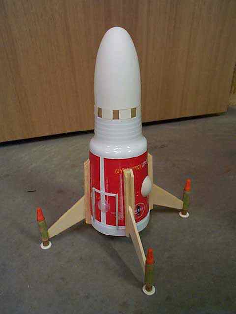
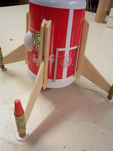
The bulges on either side of the body are ping pong ball sections attached with medium CA. I used about a 1/3 section for each bulge. The Door detail was made up from the 1/8"x 1/8" styrene strip and the thin styrene sheet. The "window" on the door section is cut from a daily use contact lens "blister"" package. The strips on the opposite side of the body are sections of scrap 3/8" wide trailing edge balsa stock.
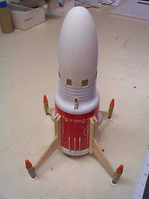
Detail along the top exposed section of body tube was done using a *" long section of scrap BT80 cut into 5/8" long sections. These are glued to the top exposed section of the body tube equally spaced around the outside.
 The engine hook is reinforced by a scrap chunk of BT50 split length-wise
and epoxied over the hook between the centering rings. Position the
rear ring *" from the rear end of the motor mount tube. Position
the whole mount in the rear of the BT80 so the back face of the ring is
*" up inside the tube. The 8" long Kevlar is tied to the forward centering
ring and looped at the free end for mounting the elastic shock cord.
The engine hook is reinforced by a scrap chunk of BT50 split length-wise
and epoxied over the hook between the centering rings. Position the
rear ring *" from the rear end of the motor mount tube. Position
the whole mount in the rear of the BT80 so the back face of the ring is
*" up inside the tube. The 8" long Kevlar is tied to the forward centering
ring and looped at the free end for mounting the elastic shock cord.
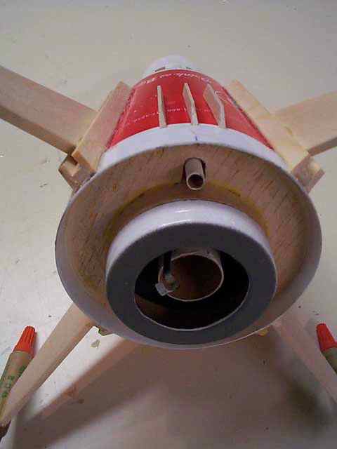
The rear of the motor mount area is capped off with the bottom section of cup cut off earlier. The remaining bit of scarp BT80 was cut at *" long, cut length wise and rolled in to fit inside the rear end of the body tube. Cut out the center of the cup bottom.. This was cut at a part of the cup bottom that already had a step molded into it. Epoxy the cup bottom onto the end of the motor mount tube. The cut section of body tube acts like a tube coupler.
 Attach the shock cord to the Kevlar mount, attached the chute, well
you know the rest of the drill.
Attach the shock cord to the Kevlar mount, attached the chute, well
you know the rest of the drill.
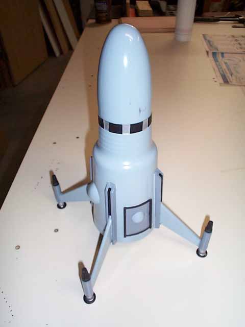
I haven't done any finishing on this yet. It hasn't flown yet either, but I hope to get out in the next few weeks and test fly it. I suspect it will need a good bit of nose weight, which I haven't added yet. I plan on using a D12-3 for the first flight.
"Lander" flight report 3-18-2001.
Light northwest breeze, sunny, temps in the upper 40's. I had added two casting "tear drop" type sinkers to the tip of the nose cone and hot glued them in place. Not sure of the total amount of weight. I will have to get a weight on the nose and the whole rocket later.
The balance point with D12-3 is approximately 3 5/8 inch from the back edge of the cup. Note: precision CG finding equipment consists of two fingers held upright with rocket rocking back and forth on finger tips :-)
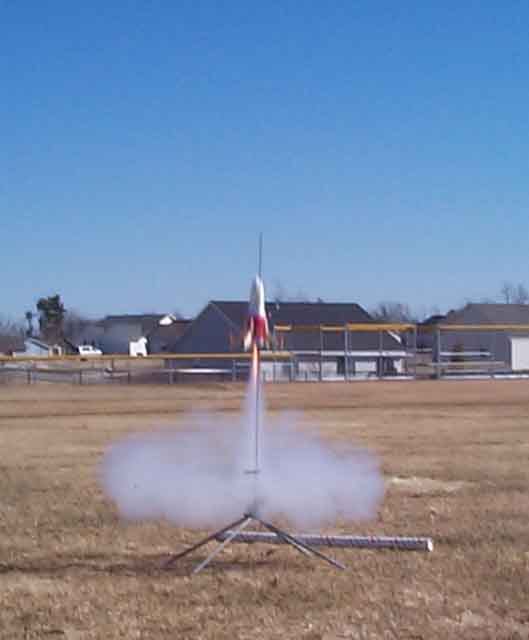
First flight was accomplished on an Estes D12-3. Boost was rock solid stable with only slight weather-cocking. I estimate it reached an altitude of around 250 feet, maybe a little higher. Ejection occured just after apogee. Recovery was on an 18 inch nylon chute. Rocket was recovered intact with the only damage being one of the micro-motors on one leg pod was knocked loose, but did not come off. A 24 inch chute may be a better choice if flying over hard ground or in calm conditions.
Now I need to come up with a better name than "Lander". Spooge Prospector maybe?
Kelo "why do I hafta name my rockets anyway can't I just call it the blue one or the red one or whatever and be done with it" Waivio
 |
 |