| Manufacturer: | Scratch |
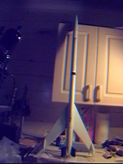
Luna 2-18 Express
Model designed and built by Donald Qualls
 propellant scoops and her passenger
cabin converted to long term living quarters and hydroponics. During that
process, in order to save mass that would contribute nothing to the mission,
her belly jets and landing gear were removed and her main propellant tank
extended an additional 14 meters past the original nose (just below the
cockpit, the original nose faired into the passenger cabin's hump); this gave
enough propellant capacity, in conjunction with the Farside Facility catapult
launch, to transit directly to Jupiter – the catapult could not be used
for a slingshot maneuver around Earth, and the propellant used to boost from
the Lunar surface or direct from Earth orbit would have been sorely missed
during Jovian insertion.
propellant scoops and her passenger
cabin converted to long term living quarters and hydroponics. During that
process, in order to save mass that would contribute nothing to the mission,
her belly jets and landing gear were removed and her main propellant tank
extended an additional 14 meters past the original nose (just below the
cockpit, the original nose faired into the passenger cabin's hump); this gave
enough propellant capacity, in conjunction with the Farside Facility catapult
launch, to transit directly to Jupiter – the catapult could not be used
for a slingshot maneuver around Earth, and the propellant used to boost from
the Lunar surface or direct from Earth orbit would have been sorely missed
during Jovian insertion.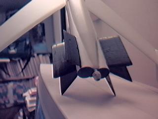 The distinctive aeroshell around the forward ends of
the engines houses the propellant pumps and the power reactor, a liquid sodium
power plant adapted to provide electricity for the 2-18 Express. This
all-nuclear system meant the 2-18 class didn't need to carry any oxidizer; the
Single-H could be catalyzed to recombine and provide very effective maneuvering
and landing jets, and of course was the best possible propellant for use in any
nuclear thermal engine. Simplified plumbing and a single tank meant still more
performance improvements over older designs – and like everything else in
aerospace, once you start saving a little mass somewhere, the savings snowball.
The distinctive aeroshell around the forward ends of
the engines houses the propellant pumps and the power reactor, a liquid sodium
power plant adapted to provide electricity for the 2-18 Express. This
all-nuclear system meant the 2-18 class didn't need to carry any oxidizer; the
Single-H could be catalyzed to recombine and provide very effective maneuvering
and landing jets, and of course was the best possible propellant for use in any
nuclear thermal engine. Simplified plumbing and a single tank meant still more
performance improvements over older designs – and like everything else in
aerospace, once you start saving a little mass somewhere, the savings snowball.
The Model
 made from 18"
of BT-50 split lengthwise with a BNC-50A (Alpha nose cone) split and
carved/sanded to fit the contour of the BT-56. The nose cone and aeroshell are
from a Maniac and a Long Shot – the aeroshell was split along the molding
seam and carved to fit the contours of the dual motor mount, then glued to the
airframe and motor mount tubes with medium CA. A small liberty was taken; I
installed a positive retention system to ensure that the motors stayed in place
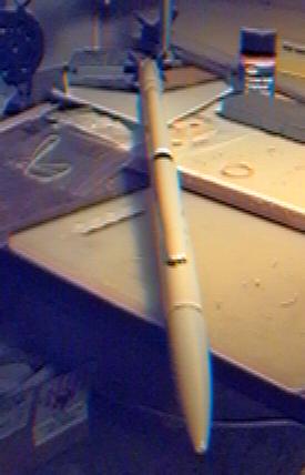
and did their job at deployment time. Unfortunately, due to a camera problem
(the operator failed to secure the film to the take up spool when loading,
resulting in a blank roll), there are no construction or flight photos; only
these images, taken with a web camera, currently exist.
made from 18"
of BT-50 split lengthwise with a BNC-50A (Alpha nose cone) split and
carved/sanded to fit the contour of the BT-56. The nose cone and aeroshell are
from a Maniac and a Long Shot – the aeroshell was split along the molding
seam and carved to fit the contours of the dual motor mount, then glued to the
airframe and motor mount tubes with medium CA. A small liberty was taken; I
installed a positive retention system to ensure that the motors stayed in place
and did their job at deployment time. Unfortunately, due to a camera problem
(the operator failed to secure the film to the take up spool when loading,
resulting in a blank roll), there are no construction or flight photos; only
these images, taken with a web camera, currently exist.
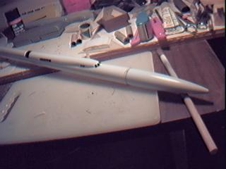
 The issue of paint schemes is a sensitive one –
the Luna originally wore the Pan Am Cunard colors, but that paint scheme
wasn't preserved when she was taken out of service, and the extensive refit
prior to the Jupiter mission didn't originally include a repaint – paint,
again, was excess mass. The actual color scheme, then, is a combination of
whatever was left of the original PAC and whatever natural finish was present
on new parts (such as the propellant tank extension and ram scoops) – the
latter frequently bare metal, since the ship wasn't expected to need protection
from oxidation.
The issue of paint schemes is a sensitive one –
the Luna originally wore the Pan Am Cunard colors, but that paint scheme
wasn't preserved when she was taken out of service, and the extensive refit
prior to the Jupiter mission didn't originally include a repaint – paint,
again, was excess mass. The actual color scheme, then, is a combination of
whatever was left of the original PAC and whatever natural finish was present
on new parts (such as the propellant tank extension and ram scoops) – the
latter frequently bare metal, since the ship wasn't expected to need protection
from oxidation.Flight Report
Building -- Parts and Plans
To built the Luna 2-18 Express you'll need the following parts:27" of BT-56
1 or 2x BT-56 couplers (mine came with an 18" section in the bag, so I
only needed one coupler, but the standard length seems to be 9" and will
need two)
2x PNC-56, same as those in the Maniac and Long Shot kits
18" of BT-50 (for passenger cabin)
1 BNC-50, balsa version of an Alpha nose cone (plastic will work also, but it's
a bit harder to split and sand to contour)
2x 6" sections of BT-20
4x 520 centering rings -- two for the baffle, two as thrust rings
4x 4" (or longer, as desired) sections of BT-5 -- or only two if you don't
build the baffle
Card stock for cutting the gas seals on the baffle
1 sheet 1/8" balsa, 3" wide, medium-hard
suitable scrap or sheet of 1/16" balsa at least 1.6" wide, medium
3/16" launch lug
Recovery system of your choice (I used a 14" Quest parachute left over
from my Big Betty's conversion to an egg lofter)
Optionally, some sort of motor retention system
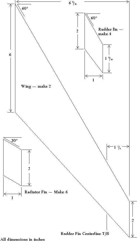
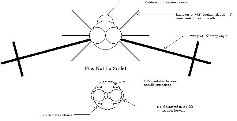
Please see the following fin alignment diagram, including baffle layout, and dimensioned fin pattern:
To construct the Luna 2-18 Express model, first join the sections of BT-56 airframe. Ensure that the sections are straight by rolling the tube on a flat surface such as a table top before the glue sets. Set aside one nose cone, it will be the actual nose cone. Split the other nose cone along the molding seam, and remove the base of the "heel" section of the cone. Cut the heel section to about 1/4" length -- this is not a critical dimension, this cut just simplifies fitting the aeroshell later one.
Sand the glassine off all the tubes to facilitate glue adhesion -- doing this now will avoid frustration later.
Mark the motor mount tubes for the locations of the radiator fins and for their glue join line. Install the 520 centering rings, two as thrust bearings about 2 1/2 inches from the rear of the tubes, the others exact at the forward ends of the tubes. Glue one BT-5 section into each forward centering rings, taking care to align the BT-5 parallel to the BT-20. Join the two BT-20 tubes side by side, with both BT-5 at the same end. Placing the tubes on a flat surface like a table top while gluing will help ensure the motor mounts are parallel.
If you're making the baffle, cut the centering rings to fit the BT-56 and the BT-5 baffle tubes, and assemble the baffle as shown in the diagram -- the BT-5 for the forward half should overlap the BT-5 from the motor mounts by about one inch, to allow for good gluing. Start by sliding one centering ring onto the BT-5 in the motor mount, leaving about 1/2" clearance from the motor mount to allow for attaching the aeroshell later; glue it in place. Slide the other centering ring over the other pair of BT-5, apply glue, and then glue those tubes to the tubes from the motor mount to for a cluster of tubes with about an inch of overlap and a baffle chamber with adequate space to avoid restriction of the ejection gas. Be very careful of alignment; roll the assembly on a table with the motor mounts hanging off the side to ensure it's all straight. Once the glue is dry, mount the assembly into the BT-56 airframe, butting the forward end of the BT-20 against the aft end of the BT-56. If you've built everything straight up to now, the motor mounts will align parallel to the airframe; if not, you can flex the mount a bit at this stage, and when the glue sets up where the BT-5 contacts the inside of the BT-56, it will lock your adjustments in place.
Once the glue is dry, carefully carve each half of the split nose cone to fit the contour of the motor mount tubes. The aeroshell halves must lie along the motor mount tubes and the shoulder end must fit into the airframe. Once you have a good fit, glue the aeroshell in place. If you'll be using a motor retention device or system, be sure to install it before permanently mounting the aeroshell, as you won't be able to afterward.
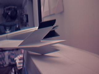
Cut all the fins. Plane and/or sand the main wings to a symmetrical airfoil, then do the same for the rudder fins and radiators. Use your choice of methods to fill the grain and tube spirals; I used Finishing Wood Filler before gluing the parts together, but everyone has their own preference. Attach the wings first, then put the rudders on the wings, and finally attach the radiators to the motor mount tubes. If you use double glue technique, white glue is more than adequate, though I recommend you use a sling type shock cord attachment to lower the rocket horizontally or slightly nose down. Don't forget to fillet -- those are very, very large fins with a surface mount.
Once the fins are in place, mark the BT-50 full length on both sides, and carefully split it along the mark. If you use a metal angle or channel as a guide, beware of the tube closing up after the first side is split, and leaving you with a helical second cut -- this is bad. Split the BNC-50 and glue the halves into the ends of the split tube. Use the airframe to mark the arc on the butt end of the nose cone halves, and then use a gouge or power sander to rough cut before sanding to final fit. Glue the passenger cabin to the airframe, ensuring the BT-50 is adhered all along both edges. Fillets here are cosmetic, but they have a big effect on the appearance of the model.
Hang in there, you're almost done! All that's left is filling and sanding, if you haven't, attaching the launch lugs, installing the recovery system, then finishing by your choice of methods. Now go fly!
 |
 |