| Manufacturer: | Scratch |
by John DeMar

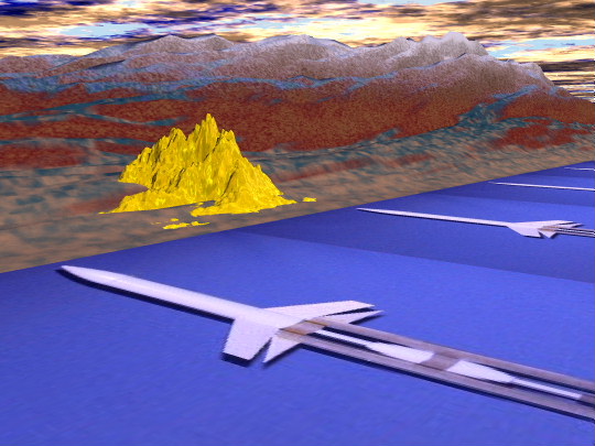
Sector Chief "Yukon
Centauri" says: "Remember where you parked"!
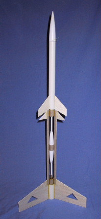 |
INTRODUCTIONThis Astron class cargo vehicle was designed specifically to handle mining material delivery to planetary objects with a moderately dense atmosphere. The primary two-stage configuration supports initial boost from the source planetoid and subsequent reentry of the cargo payload while returning the crew safely to their home base. The delivery vehicle separates from the crew return spacecraft and optimizes its energy budget through glide recovery to the cargo's destination.Other applications for the vehicle are not well documented in the fleet manuals but are known to exist. Although we are unsure of the direct nature of these excursions, reports from the 4th moon of Nymptron have indicated loud music emanating from the hull. Since the discovery of naturally occuring deposits of cheese food, lite beer, and latex in the Jovian system, over 52,094 DCg's have been produced. The Delta Mining Corporation maintains high profit margins utilizing an all-volunteer crew. |
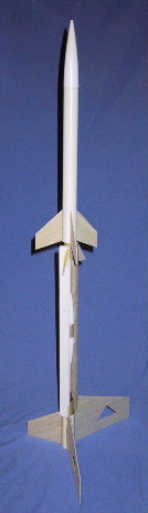  |
Parts Lists:1) Components and Packaging from one Estes Gemini DC2) Totally Tubular TT-2 tubing, 14" 3) 1" x 2" piece of 1/32" ply or G-10 (preferred) Optional: extra 3/32" balsa for upper-stage fins or make from built-up cardstock using package insert. Patterns:Glider wings, canards, and tail: [pattern1.pdf]Upper stage fins: [pattern2.pdf] Supplies:Hobby knifeRuler Sandpaper Titebond II 5-minute epoxy
|
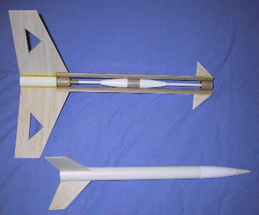
Glider Assembly:The canard-style glider is made from a 3" section of BT-50 with a 4" section of BT-20 centered inside using two centering rings. Both tubes are flush at the back end. The motor hook may be used here, but was not included in my prototype. Instead, a thrust ring was added inside the motor tube with 1/4" of the motor left showing at the rear.The top of the motor tube is plugged with a 1" section of the "motor measuring tube" (blue or yellow in the kit) or use a piece of BT-20 coupler. Block the upper portion with a disc made from the G10 (or ply) and drill a 1/4" hole in the center. Insert the TT-2 tube into this disk and epoxy the inside of the coupler and disk, leaving the tube open inside. This is used to vent the lower stage to light the upper stage.
|
The "pod" is made from the two BT-20 nosecones. Remove 1/2" of each tip and form a hole for the TT-2 vent tube to pass through. Another 1" section of BT-20 couples the two nosecones together. Slide this onto the TT-2 tube. Cut an additional 1" length of BT-20 and
glue this between the upper ends of the half-tubes. Center the TT-2 inside of
this by making another G10 (or ply) disk with 1/4" hole. Use the remaining BT-50 for the upper body tube. You may wish to make this into two pieces, reserving a 5" piece for a payload section coupled using the bulkhead block. Cut out a 3" section of BT-20 for the upper stage motor tube. Center this within the BT-50 upper stage flush with the aft end. Add a thrust ring using the rest of the "motor fit" tube. Make the shockcord mount, shockcord, and parachute in the way you prefer. Cut out the upper stage fins and glue them on. Add fillets to all joints after the glue dries. |
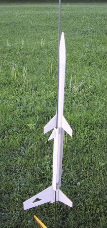
The forward 'canards' are cut from inside the main wings! 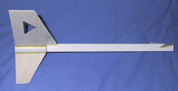 You may wish to "tissue" the glider wings for added strength. |
Glue the wings on with the upper "boom" edge aligned
with the wing. This is about 3.5" of "dihedral" at each
wing tip. Glue on the canards with about 1/4" slant upward at the forward end of the boom. Glue on the tail stabalizer. Trim for even glide by moving the pod and taping in place, or add clay to the rear between the lower fillets of the wing-body joints. |
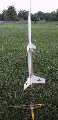  |
Flight PreparationsFriction fit the booster motor into the glider motor mount and install the igniter.Friction fit the upper stage motor into the upper stage, leaving about 1/2" sticking out the back of the motor tube. Prep the upper stage recovery system. Insert the upper stage's aft 1/2" of the motor into the forward glider tube. Alight the upper stage nozzle with the TT-2 tube. Make sure the upper-stage motor fits tightly onto the lower stage (see flight note below)! Slide the rod inside one of the boom halfs. (You may wish to add a launch lug instead). Hook up and.... |
Why is this man smiling????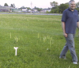 ("It wasn't me, Chief Centauri... it's the sulfur atmosphere!") 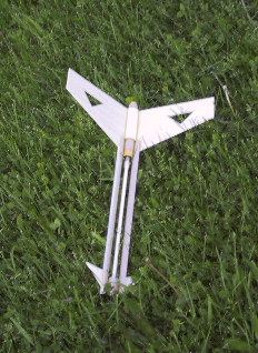 Glider without cargo pod after 1st flight. |
Flight Results:Flight 1: A10-0 stages to B6-4.Windy (5-10mph) At about 100 ft, the upper stage pops off, Both pieces are undamaged. The failure mode was that I neglected to glue in the venting tube coupler
into the top of the lower motor tube. The staging gases pushed it forward
and popped the upper stage off before ignition. There was some scorching
on the nozzle of the upper stage but it didn't have enough time to light. Flight 2: B6-0 staged to B6-4. Staged and glided nicely! Lost the upper half, but it's the simpler portion to replace. Note: the 1/4" venting tube may need to be replaced after a few flights. ENJOY! |
After the Rush of 4049, lone prospectors were displaced by unemployed
Cheese Weasels.
Contact: John DeMar, NAR #52094
Flight photos by Steven DeMar.
Other photos, patterns, and 3D Art by John DeMar.
 |
 |